


to-noise performance since the signal is now closer to the noise floor. Because users of digital equipment have to be
extremely careful not to exceed 0 dB FS (full-scale), they must use peak-reading headroom meters. On the other hand,
the forgiving nature of analog tape allows users of analog recording equipment the luxury of only needing to monitor
the average level using VU meters, often having no peak indicators whatsoever. If only digital were more forgiving like
analog, we could really exploit its wide dynamic range and more completely capture the essence of the musical perfor-
mance.
Enter the dbx Type IV™ Conversion System. Like its related predecessor technologies—Type I™, Type II™, and
Type III™—dbx Type IV™ succeeds in preserving the wide dynamic range of the original analog signal within a limit-
ed dynamic range medium. Whereas Type I™ and Type II™ expand the dynamic range of analog tape and other limit-
ed dynamic range media, and the simultaneous encode/decode process of Type III™ similarly expands the limited
dynamic range through minimum-delay devices, Type IV™ breaks new ground by greatly enhancing the useable dynam-
ic range of the analog-to-digital conversion process.
The dbx Type IV™ Conversion System combines proprietary analog and digital processing techniques to cap-
ture a much wider dynamic range than the A/D converter could by itself, preserving the maximum amount of informa-
tion from the analog signal. This information is then encoded within the available bits of whichever A/D converter is
used. This means that Type IV™ improves the performance of any A/D converter, from low-cost 16-bit to high-perfor-
mance 24-bit! And no decoding is necessary beyond the conversion process!
As we have previously mentioned, digital systems have a wide linear region compared to analog tape and the
dynamic range of A/D converters has improved significantly in recent years. The dbx Type IV™ Conversion System takes
advantage of this and utilizes the top 4 dB of the A/D converter’s linear dynamic range to create a logarithmic “overload
region.” This allows high-level transient signals passing far above the point where the overload region begins to be ade-
quately represented in just 4 dB of the converter’s dynamic range, whereas a typical A/D converter would clip. With
Type IV™, you can never clip the A/D converter!
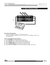
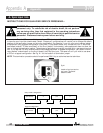
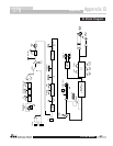
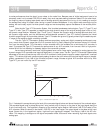
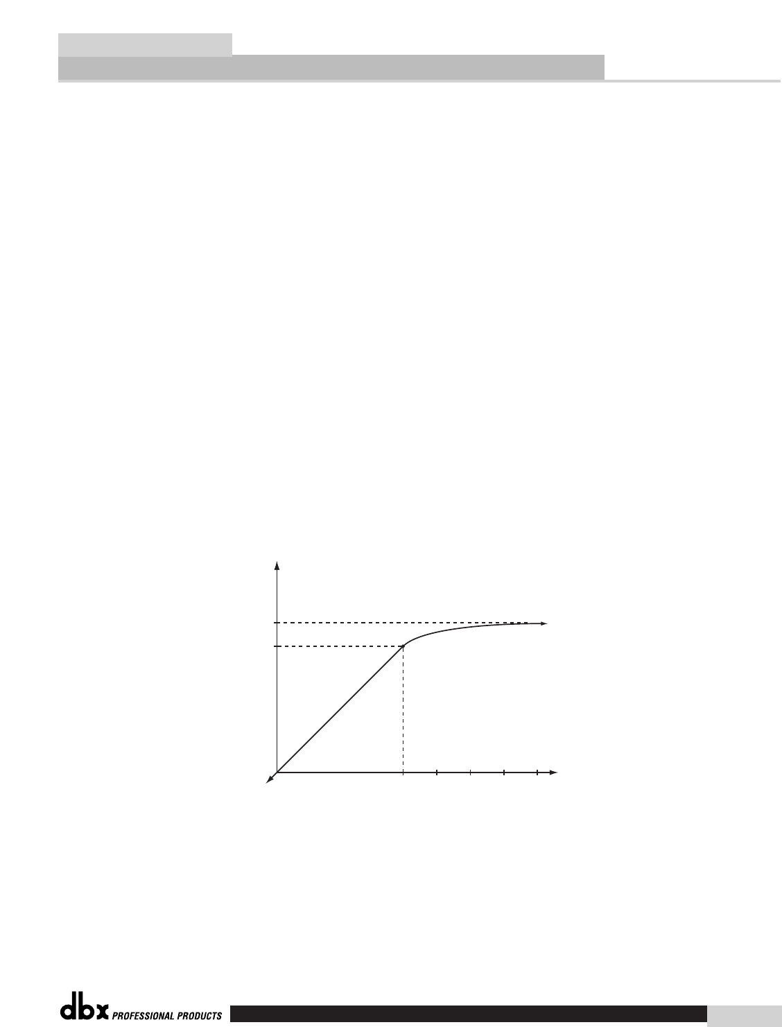
Fig. 1 illustrates this concept showing the level of the converted signal below and above the start of the overload region.
The converted signal level is plotted along the Y-axis (vertical axis) of the plot vs. the level of the input signal along the
X-axis (horizontal axis). The logarithmic mapping of the overload region begins 4 dB below 0 dB FS (full-scale) of the
A/D converter. What this shows is that below -4 dB FS, in the linear region, the output signal is the same as the input
signal. Above this, in the logarithmic region, high-level input signals get “mapped” into the top 4 dB of the A/D con-
verter. This mapping is analogous to the signal compression effect that occurs when recording high-level signals onto
analog tape.
L
o
g
a
r
i
t
h
m
i
c
R
e
g
i
o
n
-4
-4
0 +4 +8 +12
dB
dB FS
Input
Signal
Level
Converted
Signal
Level
Linear Region
0
A/D Clip Point
Figure 1 - Converted Level vs. Input Level
Type IV™ White Paper
Appendix C
376 User Manual
®
23
376