


Getting Started
®
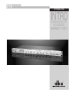
376 User Manual
2
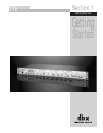
Section 1
376
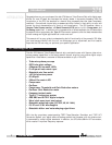
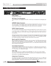
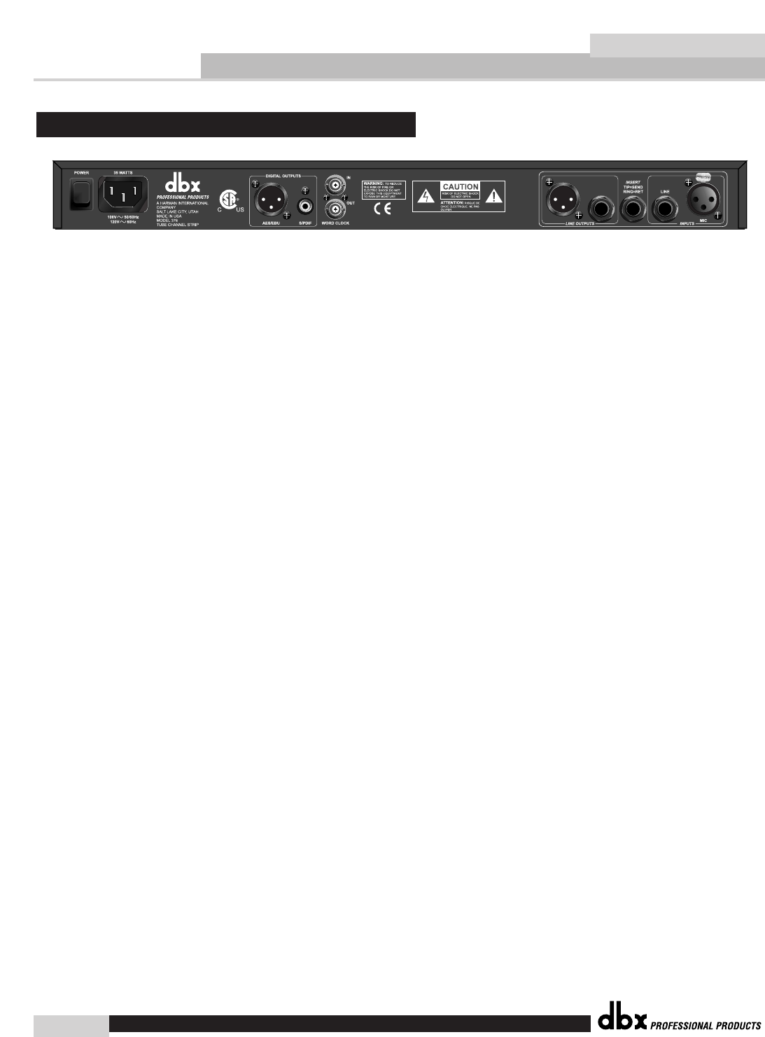
Power Switch
Turns the 376 on and off.
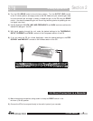
IEC Power Cord Receptacle
This is the power cord receptacle of the 376. An IEC cord is included with the shipped prod-
uct.
AES/EBU Digital Connector
The 376 provides AES/EBU digital output formatting through the XLR connector. Be sure to
use short lengths of 110 Ωdigital cables rather than standard XLR to XLR cables. Using the
correct cables will prevent digital dropouts and other interconnection problems.
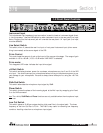
S/PDIF Digital Connector
The 376 provides S/PDIF digital output formatting through the RCA coaxial connector. Be sure
to use short lengths of 75 Ωdigital cables or 75 Ωvideo cables rather than standard audio RCA
to RCA cables. Using the correct cables will prevent digital dropouts and other interconnec-
tion problems.
NOTE: Although digital information is coming out of both XLR and RCA jacks simultaneously, the correct format will
only appear at the output for the format type selected. For example, if you have AES/EBU format selected, an AES/EBU
formatted signal will appear at the output of both the XLR and the RCA connector. Or, if you have S/PDIF format select-
ed, an S/PDIF formatted signal will appear at the output of both the RCA and XLR connectors.
Sync In and Out Connectors
BNC connectors are provided for both clock in and out functions. The 376’s clock chips are dbx
custom VCXO chips, designed for low-jitter performance. You may use the 376 as a master
clock source, having other equipment slave to the 376, or you may slave the 376’s clock to any
other wordclock source device.
Line Output Connectors
The analog output section of the 376 offers both XLR and 1/4" TRS electronically balanced con-
nections. The 1/4” connector may be used in a balanced or unbalanced configuration. Using a
1/4” TS connector will unbalance the signal.
Insert Jack
The 1/4” TRS Insert jack (Tip=SEND and Ring=RETURN), will allow you to add an effects
loop directly into the signal path of the 376. This insertion point is located after the tube sec-
tion and prior to the signal processing section.
Analog Input Connectors
The analog input section of the 376 offers both XLR (Microphone) and a rear 1/4" TRS (Line)
electronically balanced connections. The 1/4” connector may be used in a balanced or unbal-
anced configuration. Using a 1/4” TS connector will unbalance the signal.
1.1 Rear Panel Connections