


9
Models 2E510E, 2E511E, 3E218E, and 3E219D
Dayton Operating Instructions and Parts Manual
104447
®
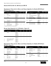
Maintenance (Continued)
NOZZLE
1. Remove upper shell (See page 6).
2. Remove fan (See page 6).
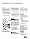
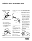
3. Remove fuel and air line hoses from
nozzle assembly (See Figure 18, 19,
or 20).
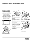
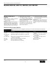
4. Turn nozzle assembly 1/4 turn to
left and pull toward motor to
remove (See Figure 21).
5. Place plastic hex-body into vise and
lightly tighten.
6. Carefully remove nozzle from the
nozzle adapter using 5/8" socket
wrench.
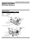
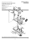
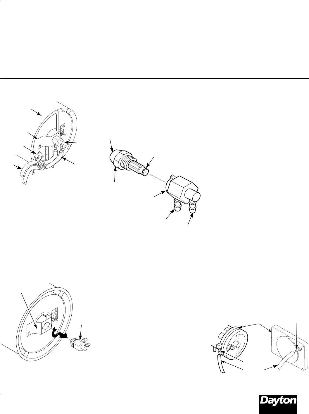
Nozzle
Assembly
Burner Strap
Figure 20 - Removing Air and Fuel Line
Hoses (150,000 Btu/Hr Model Only)
Fuel Line
Hose
7. Blow compressed air through face
of nozzle. This will free any dirt in
nozzle area.
8. Inspect nozzle sleeve for damage.
9. Replace nozzle into nozzle adapter
until nozzle seats. Tighten 1/3 turn
more using 5/8" socket wrench (40-
45 inch-pounds).
10. Attach nozzle assembly to burner
strap.
11. Attach fuel and airline hoses to
nozzle adapter assembly. See Fuel
and Air Line Replacement and
Proper Routing.
12. Replace fan (See page 6).
13. Replace fan guard and upper shell.
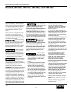
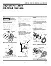
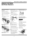
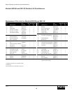
Air Line
Fitting
Fuel Line
Fitting
Nozzle
Nozzle
Sleeve
Nozzle
Face
Figure 22 - Nozzle and Nozzle Adapter,
All Models
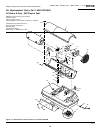
Combustion
Chamber
Nozzle/
Adapter
Assembly
Air Line
Hose
Nozzle Adapter
Figure 21 - Removing Nozzle Assembly,
All Models
Photocell
Bracket
Burner
Strap
FUEL AND AIR LINE REPLACEMENT
AND PROPER ROUTING
1. Remove upper shell (see page 6).
2. Remove side cover screws using
5/16" nut driver.
3. Remove side cover.
4. Inspect fuel and air line hoses for
cracks and/or holes. If fuel line hose
is damaged, disconnect from
nozzle adapter (see Figure 18, 19,
or 20) and from fuel filter (see
page 7). If air line hose is damaged,
disconnect from nozzle adapter
(see Figure 18, 19, or 20) and from
barb fitting on pump end cover
(see Figure 23).
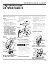
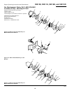
5. Install new air and/or fuel line.
Attach one end of air line hose to
barb fitting on pump end cover
(see Figure 23) and the other end
to nozzle adapter (see Figure 18,
19, or 20). Attach one end of fuel
line hose to fuel filter (see page 7)
and the other end to nozzle
adapter (see Figure 18, 19, or 20).
Note: Route hoses as shown in
Figure 18, 19, or 20 according to
Model. Hoses are not to touch
photocell bracket.
6. Replace side cover.
7. Replace upper shell and fan guard
(see page 6).
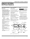
Barb Fitting
Air Hose
Pump End Cover
Barb
Fitting
115,000 Btu/Hr
Model
40/60,000 Btu/Hr
Models
Figure 23 - Air Hose to Barb Fitting