


19
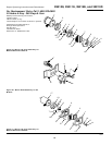
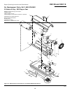
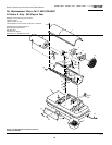
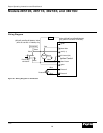
Models 2E510E, 2E511E, 3E218E, and 3E219D
Dayton Operating Instructions and Parts Manual
104447
®
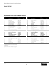
Ref. Part
No. Description Number Qty.
Ref. Part
No. Description Number Qty.
1 Upper Shell 098511-164 1
2 #10-16 x 1/2" Screw * 100647-01 8
3 Combustion Chamber 098512-59 1
4 Photocell Bracket 099229-01 1
5 #6-32 x 3/8" Screw * M10908-2 2
6 Photocell Assembly M16656-24 1
7 Burner Head Assembly † 1
8 #10-16 x 1/2" Screw * M11084-27 2
9 Fan 102042-01 1
10 Motor and Pump Assembly † 1
11 Rubber Bumper M50631 2
12 Motor Mounting Bracket 101206-01 1
13 Button Plug 101695-01 1
14 Ignition Control Assembly 104068-02 1
15 1/4-20 Hex Lock Nut NTC-4C 2
16 Fan Guard M51114-01 1
17 Drain Plug (includes O-ring) M27417 1
18 Button Plug 099213-01 1
19 Fuel Line M51345-06 1
20 Fuel Filter 099743-01 1
21 Fuel Line Tube M51151-02 1
22 Rubber Bushing M10990-3 1
23 Airline M50814-03 1
24 Lower Shell 098511-163 1
25 Bushing M50104-03 2
26 Bushing M50104-01 2
27 #10-16 x 1/2" Screw *M11084-27 6
28 Clip Nut M11271-8 8
29 #8-32 x 3/8" Screw *M10908-14 1
30 Fuel Tank 098513-67 1
31 Fuel Cap (Includes Gasket) 097702-01 1
32 P.C. Board Support 102349-01 5
33 Strain Relief Bushing M11143-1 1
34 Power Cord 098219-24 1
35 Side Cover M51077-09AA 1
36 #10-16 x 1/2" Screw *M11084-27 4
37 Thermostat 097657-03 1
38 #6-32 x 1/4" Screw M10908-1 2
39 Thermostat Knob 104905-01 1
∆ Wire Clip (Secures Wires 099650-01 1
of Thermostat)
∆ Wire Tie 103814-01 1
(*) Standard hardware item, available locally.
(∆) Not shown.
(†) Not available as an assembly, see page 13.
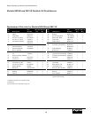
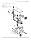
Model 3E219D
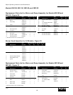
Replacement Parts List for Model 3E219D