


Dayton Operating Instructions and Parts Manual
10
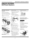
Dayton Portable
Oil-Fired Heaters
®
104447
2E510E, 2E511E, 3E218E, and 3E219D
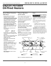
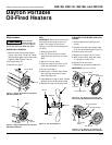
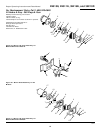
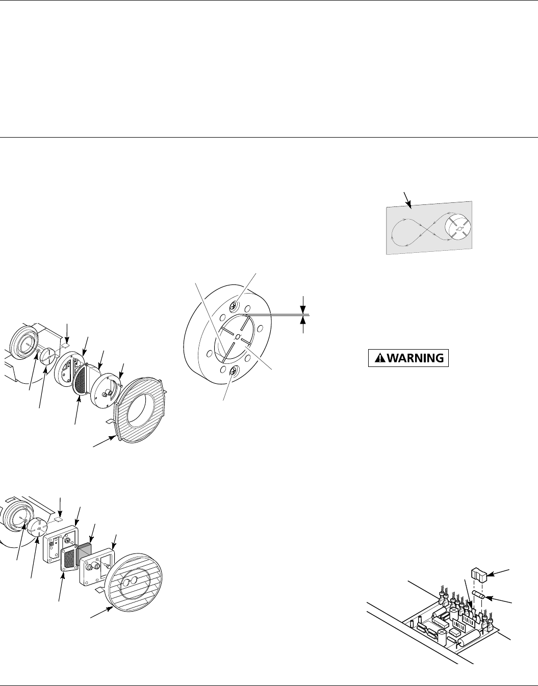
Figure 26 - Gap Adjusting Screw
Locations
NOTE: Rotate rotor one full turn to
insure the gap is .003"/.004" at
tightest position. Adjust if needed.
10. Install blades, pump plate, air
filters, and filter end cover.
11. Replace fan guard and upper shell.
12. Adjust pump pressure (See page 7).
NOTE: If rotor is still binding, proceed
as follows.
13. Perform steps 1 through 6 (See
page 9, Pump Rotor section).
14. Place fine grade sandpaper (600
grit) on flat surface. Sand rotor
lightly in “Figure 8” motion four
times (See Figure 27).
Sandpaper
Figure 27 - Sanding Rotor
Maintenance (Continued)
5. Remove pump plate.
6. Remove rotor, insert, and blades.
7. Check for debris in pump. If debris
is found, blow out with com-
pressed air.
8. Install insert and rotor.
9. Check gap on rotor. Adjust to
.003"/.004" if needed (See Figure 26).
15. Reinstall insert and rotor.
16. Perform previous steps 10 through 12.
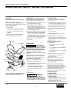
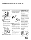
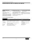
IGNITION CONTROL ASSEMBLY
(PROCEDURE FOR REPLACING FUSE ON
MODELS 3E218E AND 3E219D)
High Voltage!
Figure 28 - Replacing Fuse
Fuse
Fuse
Cover
Fuse
Clips
1. Unplug heater.
2. Remove side cover screws (4) using
5/16" nut-driver to expose ignition
control assembly.
3. Remove fuse cover.
4. Remove fuse from fuse clips.
5. Replace fuse with fuse of the same
type and rating (GMA-10). Do not
substitute a fuse with a higher
current rating.
6. Replace fuse cover.
7. Replace side cover.
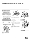
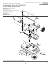
.003"/.004"
Gap
Measured
With
Feeler
Gauge
Blade
Rotor
Gap Adjusting Screw
Gap Adjusting Screw
Figure 25 - Rotor Location, Models
3E218E and 3E219D
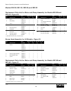
O
R-Domestic PFA/P 059A
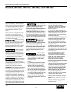
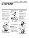
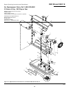
Blade
Pump Plate
Air Intake Filter
Filter End Cover
Insert
Rotor
Air Output Filter
O
TOR-Domestic
PFA/P 056B
Pump Plate
Blade
Air Intake Filter
Filter End Cover
Insert
Rotor
Air Output Filter
Figure 24 - Rotor Location, Models
2E510E and 2E511E
PUMP ROTOR
(Procedure if rotor is binding)
1. Remove upper shell (See page 6).
2. Remove filter end cover screws using
5/16" nut-driver (See Figures 24 and
25).
3. Remove filter end cover and air
filters.
4. Remove pump plate screws using
5/16" nut-driver.
Fan Guard
Fan Guard