


5
Models 2E510E, 2E511E, 3E218E, and 3E219D
Dayton Operating Instructions and Parts Manual
104447
®
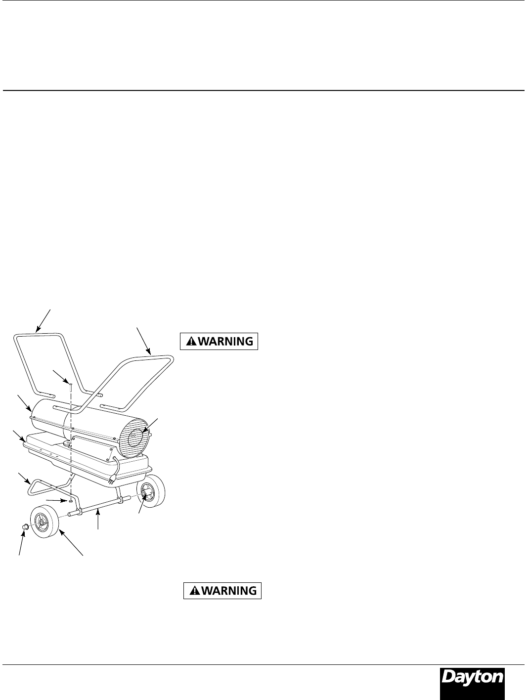
Assembly
(For Models 3E218E and 3E219D Only)
These models are furnished with
wheels and handles. Wheels, handles,
and the mounting hardware are found
in the shipping carton.
TOOLS NEEDED
• MEDIUM PHILLIPS SCREWDRIVER
• 3/8" Open or Adjustable Wrench
• Hammer
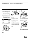
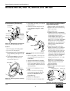
1. Slide axle through wheel support
frame. Install wheels on axle.
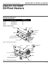
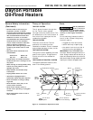
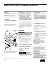
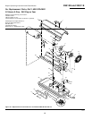
Figure 6 - Wheel and Handle Assembly,
Models 3E218E and 3E219D Only
IMPORTANT: When installing wheels,
point extended hub of wheels toward
wheel support frame (See Figure 6).
2. Place cap nuts on axle ends. Gently
tap with hammer to secure.
3. Place heater on wheel support
frame. Make sure air inlet end (rear)
of heater is over wheels. Line up
holes on fuel tank flange with holes
on wheel support frame.
4. Place front handle and rear handle on
top of fuel tank flange. Insert screws
through handles, fuel tank flange,
and wheel support frame. Attach nut
finger tight after inserting each screw.
5. After inserting all screws, tighten
nuts firmly.
Ventilation
Follow the mini-
mum fresh, outside
air ventilation requirements. If proper
fresh, outside air ventilation is not
provided, carbon monoxide poisoning
can occur. Provide proper fresh,
outside air ventilation before running
heater.
Provide a fresh air opening of at least
three square feet for each 100,000
Btu/Hr rating. Provide extra fresh air if
more heaters are being used.
Example: A 150,000 Btu/Hr heater
requires one of the following:
• a two-car garage door (16-foot-wide
opening) raised 3.5 inches
• a single-car garage door (9-foot-
wide opening) raised 6 inches
• two, 30-inch windows raised 11
inches
Screw
Extended
Hub
Axle
Nut
Hot Air
Outlet
Air
Inlet
Cap Nut
Front Handle
Rear Handle
Review and
understand the
warnings in the General Safety
Information section. They are needed
to safely operate this heater. Follow
all local codes when using this heater.
Operation
TO START HEATER
1. Follow all ventilation and safety
information.
2. Locate heater to provide maximum
circulation of the heated air. Follow
all location requirements noted in
General Safety Information, page 3.
3. Fill fuel tank with Kerosene or No. 1
fuel oil.
4. Attach fuel cap.
5. Turn thermostat knob clockwise to
the HIGH position.
6. Plug power cord of heater into
three-prong, grounded extension
cord. Extension cord must be at least
six feet long.
EXTENSION CORD WIRE SIZE
REQUIREMENTS
• 6 to 10 feet long, use 18 AWG
rated cord.
• 11 to 100 feet long, use 16 AWG
rated cord.
• 101 to 200 feet long, use 14 AWG
rated cord.
7. Plug extension cord into standard
120 Volt/60 hertz, three-hole,
grounded outlet.
Note: Ignitor will preheat for five
seconds, then heater will start.
8. Adjust thermostat knob to the
desired setting.
Note: A cold heater may affect the
thermostat setting. Further adjust-
ments may be needed until the heater
cycles at the desired setting. This
thermostat is a general-heating
control. It is not intended for precise
temperature control.
TO STOP HEATER
Unplug extension cord from outlet.
TO RESET HEATER
1. Unplug extension cord from outlet
and wait 10 seconds (two minutes if
heater has been running).
2. Repeat steps under To Start Heater.
Fuel
Tank
Flange
Wheel Support
Frame
Wheel