


7
Models 2E510D, 2E511D, 3E218D, and 3E219C
Dayton Operating Instructions and Parts Manual
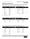
101421
®
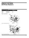
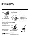
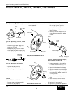
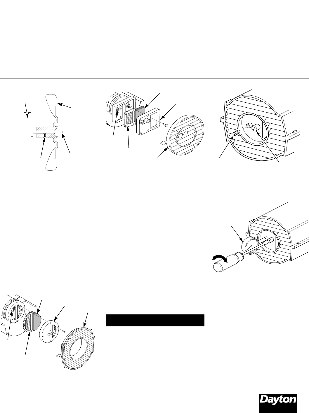
Figure 12 - Fan Cross Section, Model
3E219C
AIR OUTPUT, AIR INTAKE, AND LINT
FILTERS
1. Remove upper shell (see Figure 10).
2. Remove filter end cover screws using
5/16" nut-driver.
3. Remove filter end cover.
4. Replace air output and lint filters.
5. Wash and dry with soap and water
or replace air intake filter.
6. Replace filter end cover.
7. Replace fan guard and upper shell.
IMPORTANT: Do not oil filters.
Maintenance (Continued)
Lint Filter
Air Output Filter
Fan
Motor
5. Remove pressure gauge. Replace
pressure gauge plug in filter end cover.
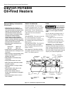
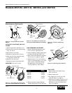
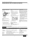
Figure 14 - Air Output, Air Intake, and
Lint Filters, Models 3E218D and 3E219C
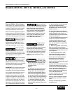
Air Output
Filter
Lint
Filter
Fan Guard
Air Intake Filter
Filter End Cover
Pump
Model Pressure
2E510D 3.0 PSI
2E511D 3.4 PSI
3E218D 4.5 PSI
3E219C 5.0 PSI
Figure 15 - Pressure Gauge Plug
Removal
Pressure
Gauge Plug
Relief
Valve
PRESSURE ADJUST
P
Pressure
Gauge
Figure 16 - Adjusting Pump Pressure
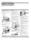
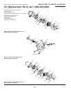
FUEL FILTER
1. Remove side cover screws using
5/16" nut-driver.
2. Remove side cover.
3. Pull upper fuel line off fuel filter
neck (see Figure 17, page 8).
4. Carefully pry bushing, fuel filter, and
lower fuel line (Models 3E218D and
3E219C only) out of fuel tank (see
Figure 18, page 8).
Figure 13 - Air Output, Air Intake, and
Lint Filters, Models 2E510D and 2E511D
Setscrew
Motor
Shaft
Air Intake Filter
Filter End Cover
Fan Guard
PUMP PRESSURE ADJUSTMENT
1. Remove pressure gauge plug from
filter end cover (see Figure 15).
2. Install accessory pressure gauge (part
number HA1180) (see Figure 16).
3. Start heater (see Operation, page 5).
Allow motor to reach full speed.
4. Adjust pressure. Turn relief valve to
right to increase pressure. Turn relief
valve to left to decrease pressure.
See specification chart below for
correct pressure for each model.