


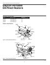
Dayton Operating Instructions and Parts Manual
10
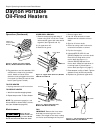
Dayton Portable
Oil-Fired Heaters
®
101421
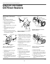
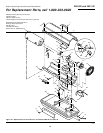
Maintenance (Continued)
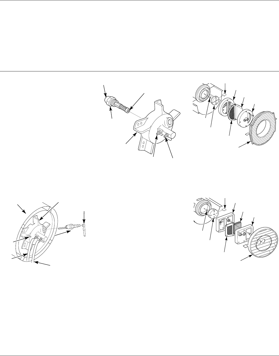
NOZZLE
(Models 3E218D and 3E219C)
1. Remove upper shell (see page 6).
2. Remove fan (see page 6).
3. Remove fuel and air line hoses
from burner head.
4. Remove spark plug wire from spark
plug.
5. Remove spark plug from burner
head using 13/16" open-end
wrench.
6. Remove three screws using 5/16"
nut-driver and remove burner head
from combustion chamber.
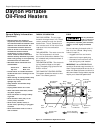
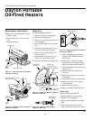
Burner
Head
Air Line
Fitting
Fuel
Line
Fitting
Nozzle Sleeve
Nozzle
Nozzle Face
Figure 28 - Removing Nozzle, Models
3E218D and 3E219C
10. Inspect nozzle sleeve for damage.
11. Replace nozzle into burner head and
tighten firmly (80-110 inch-pounds).
12. Attach burner head to combustion
chamber.
13. Install spark plug in burner head.
14. Attach spark plug wire to spark plug.
15. Attach fuel and airline hoses to
burner head.
16. Replace fan (see page 6).
17. Replace fan guard and upper shell.
7. Place burner head into vise and
lightly tighten.
8. Carefully remove nozzle from
burner head using 5/8" socket
wrench (see Figure 28).
9. Blow compressed air through face
of nozzle. This will free any dirt in
nozzle area.
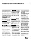
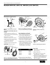
Spark
Plug
Wire
0
0 BURNER HEAD DOM. PFA/P 021A
Burner Head
Spark Plug
Fuel Line
Hose
Air Line
Hose
Figure 27 - Removing Burner Head,
Models 3E218D and 3E219C
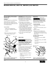
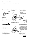
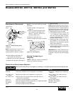
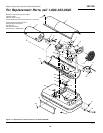
Figure 30 - Rotor Location, Models
3E218D and 3E219C
O
R-Domestic PFA/P 059A
Blade
Pump Plate
Air Intake Filter
Filter End Cover
Insert
Rotor
Air Output Filter
OTOR-Domestic
PFA/P 056B
Pump Plate
Blade
Air Intake Filter
Filter End Cover
Insert
Rotor
Air Output Filter
Figure 29 - Rotor Location, Models
2E510D and 2E511D
Screw
Combustion
Chamber
PUMP ROTOR
(Procedure if rotor is binding)
1. Remove upper shell (see page 6).
2. Remove filter end cover screws
using 5/16" nut-driver.
3. Remove filter end cover and air
filters.
4. Remove pump plate screws using
5/16" nut-driver.
Fan Guard
Fan Guard
5. Remove pump plate.
6. Remove rotor, insert, and blades.
7. Check for debris in pump. If debris is
found, blow out with compressed air.
8. Install insert and rotor.
9. Check gap on rotor. Adjust to .003"/
.004" if needed (see Figure 31,
page 11).