


Can
adian Comfort Industries V04 20 PELPRO OWNERS MANUAL
Copyright 2004
www.pelprostoves.com Dansons Group Inc.
4
18”
8”
6”
Wood Frame
Construction
Stand Offs
Part ACI-3HZ
6”
2” Min.
Air gap
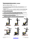
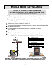
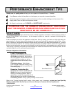
Horizontal Vent Installation
Exterior Wall
Wood Surround
Shroud
3” minimum
air gap
Wall Band /
Support Brkt
every 5’
Clean Out Tee
10’
2’
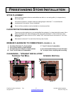
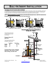
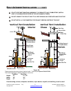
BUILT-IN INSERT INSTALLATION
CAUTION: DO NOT BLOCK VENT OPENING
The PELPRO Insert may be framed directly into a wall as either a horizontal or vertical vent installation see (figure
27, 28). The exhaust installation requirements are the same as for a freestanding stove. Refer to “Installing your
Freestanding Stove” for information concerning installation and proper hook-up of the exhaust.
NOTE: Built-In Installations require Enclosure Kit #ACI-3HZ Horizontal Vent or #ACI-3VL Vertical Vent.
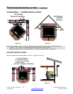
Dimensions that will be enclosed within the frame work are:
This example shows the
exhaust venting out and
up vertically
Requires Spacer Kit
#ACI-3HZ
The framed opening for this
Installation needs to be:
Tradition Bay View
Height 21” 21 - 25”
Width 30” 30”
Depth 17” 17”
If constructing a chase, adequate
Insulation, vapor barrier, drywall,
And caulking must be used.
FIGURE 27
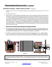
24”
18 3/4”
Shroud 1”
+
+
6 1/2”
7 3/4”
8 1/4”
3 ½”
Exhaust
Air Inlet
24”
24 3/4”
12 1/4” 10 3/4”
Traditional Insert / Built-In
24”
19”
-
23”
Shroud 1”
12 1/4” 10 3/4”
+
Exhaust
26”
+
24”
6 ½”
Exhaust
+
Air Inlet
8 1/4”
7 3/4”
3 ½”
Bay View Insert / Built-In
Adjustable
Hopper