


Below are the two most common mounting
options.
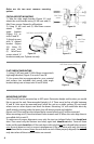
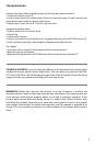
CIRCULAR POST MOUNTING
1). Take the right angle bracket (Figure 3-1) and
attach the cross bracket using (2) M4 nuts and (2)
M4x12mm screws. Repeat for all brackets.
2). Using (2) M5 nuts and (2) M5x18mm screws
attach right
angle bracket
(Figure 3-2) to
units ‘A’ and ‘B’.
3). Attach to post
with ‘U’ shaped
bracket (Figure
3-3) . Using (2)
M5 nuts and
(2) M5x27mm
screws attach ‘U’
bracket around post. Tighten securely.
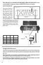
FLAT SURFACE MOUNTING
1). Using (2) M5 nuts and (2) M5x18mm screws attach
right angle bracket (Figure 4) to units ‘A’ and ‘B’.
2). Use screws that are appropriate for your material
and surface (not included) and mount right angle
bracket taking care to keep units ‘A’ and ‘B’ level.
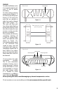
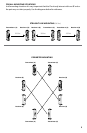
MOUNTING OUTSIDE
Units ‘A’ and ‘B’ can be mounted up to 300’ apart. Determine height and location you would
like to mount the unit. Recommended height is 3-4’. There must be line of sight between
‘A’ and ‘B’. Units must be mounted level. Install the unit on a stable surface. Do not install
where trees or other objects can block the beam. Mounting 3-4’ will avoid false alerts by
small animals crossing under the beam, but still detect people and vehicles.
Mount unit ‘B’ rst and face the infrared holes toward where unit ‘A’ will be mounted.
When mounting unit ‘A’, face the infrared holes towards unit ‘B’. When the units align there is
an audible click in unit ‘A’.
To make sure of proper alignment cover only the top two infrared holes. Unit should not
alert. Then cover only the bottom two holes, again unit should not alert. Cover all three
holes and the unit should alert. If the unit alerts with only the top two infrared holes covered,
raise the unit about an inch to correct misalignment. If the unit alerts with only the bottom
two infrared holes covered, lower the unit about an inch. When properly aligned, the unit will
only alert when all three infrared holes are covered.
Figure 3-1
M4x12mm
screws
M4 nuts
Figure 3-2
M5x18mm screws & M5 nuts
Figure 3-3
M5x27mm
screws
M5 nuts
Figure 4
M5x18mm screws & M5 nuts
4