


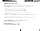
4 5
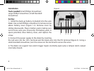
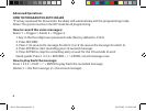
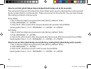
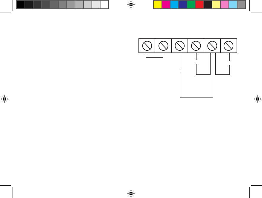
TAMPER ALARM: The tamper alarm is alarmed
when the button on the back of the dialer
(Figure 1-3) is depressed. If the tamper output is
to be used it is important to be sure the button is
depressed when the unit is mounted. The tamper
terminals can be connected to any existing
security system or alarm that accepts a normally
closed input trigger. If the tamper output is not
connected to any system, the jumper wire must
remain between these terminals.
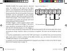
TR1/TR2: Triggers 1 and 2 support sensors with
normally open outputs. For Trigger 1, the sensor
wires would be connected to the TR1 terminal
and the OV terminal (Figure 2). For Trigger 2,
the sensor wires would be connected to the TR2 terminal and the OV terminal. (Note: Since these
terminals are simply “switches” there is no positive or negative. The wires can be hooked up either
way.)
5. Plug the supplied phone cord into the “LINE” jack (Figure 1-4) and then into your home phone
jack. If you wish to connect a phone at the dialer location, you can connect the phone to the
“PHONE” jack (Figure 1-5) on the dialer.
6. Continue on to the Advanced Operations to program your dialer or refer to the “AD-01 Quick
Reference Programming” on page 14.
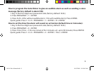
TAMP TR2 TR1 OV 12V+
Trig 2
Trig 1
12V
OV = Universal Ground
Figure 2 (from Figure 1-1)
AD-01 Slave Manual.indd 5 10/15/2009 10:20:44 AM