


I. INSTALL THE PURIFICATION ASSEMBLY AND
STORAGE TANK
For Basement Installation See Installation Instructions O.
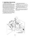
Undercounter Installation:
The purification assembly is usually mounted to the right or
the left side wall inside of the sink cabinet, taking into consider-
ation the space available and the tank location. Generally, the
storage tank is placed in the rear of the sink cabinet while the
purification assembly is positioned toward the front for filter
cartridge accessibility.
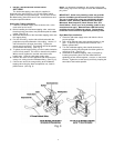
To mount the purification assembly, elevate it at least 2" (5
cm) off of the cabinet floor and, while keeping it level, mark the
location of the mounting holes on the cabinet side wall. Make
small pilot holes with an awl or a drill and screw in the two
mounting screws; leaving just enough protruding to allow the
bracket mounting slots to slide over them.
NOTE: If the cabinet side walls are not of solid construction,
the purification assembly can be set on the cabinet floor and
held against the side wall with the mounting screws. However,
the purification assembly will then need to be lifted from the
mounting screws in order to remove the filter cartridges.
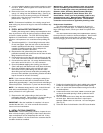
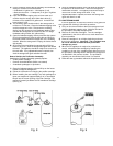
The storage tank may be oriented either vertically or horizontally.
It is generally placed to the rear of the cabinet but can be set in
the front center (between the sink basins) for ease of access if
space permits. For horizontal positioning, carefully detach the
tank base from the tank bottom and use it as a cradle.
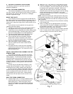
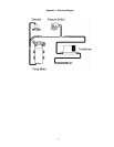
J. MAKE THE TUBING CONNECTIONS
With all of the components in place, the tubing connections
can be made. When routing the tubing between the compo-
nents, several guidelines should be observed.
• Tubing runs should generally follow the contour of the
cabinet rather than interfere with the cabinet storage area.
• Strive for a neat and orderly tubing “flow” by using
fasteners (e.g. insulated staples) to secure the tubing.
• Arrange the tubing so that there are no sharp bends.
Leave some “play” in the tubing for ease of servicing, then
cut the tubing to the desired length.
• Try to keep the tubing from the purification assembly to the
tank and faucet as short as practical for good flow.
For Basement Installation See Installation Instructions O.
Undercounter Installation:
The appliance will have the 3/8” yellow, 3/8” blue and the
special red SFC tubing already connected to the purification
assembly.
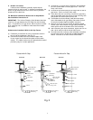
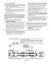
1) The 1/4” orange tubing should already have been
connected to the feedwater tapping valve. Route the other
end through the large opening in the bottom of the metal
bracket and loop it back to the “Feed” connection on the
purification assembly.
2)
Attach the 1/4” x 3/8” union to 1/4” blue tubing on faucet.
3) Connect the 3/8” blue tubing from the purification
assembly to the other end of 3/8” x 1/4” union.
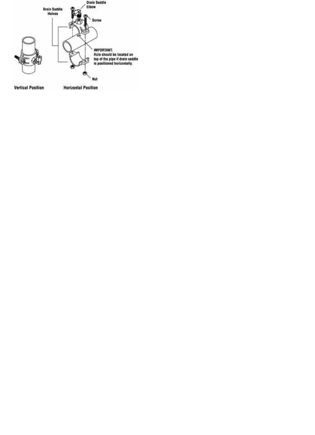
4)
Route the 3/8” black tubing from the faucet air gap to the
drain saddle so that it slopes continuously downward
without any loops or low spots. Cut the tubing to the
proper length and connect it to the drain saddle elbow.
5) Connect the 3/8” yellow tubing from the purification
assembly to the tank.
6) Route the special red SFC tubing toward the faucet. Do
not cut this special SFC tubing
. It’s length is important
to maintain proper efficiency and performance.
7) Cut the 1/4” green tubing from the faucet air gap to the
proper length and connect it to the1/4” connector fitting on
the end of the SFC tubing.
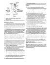
K. INSTALL THE ICEMAKER HOOKUP (optional)
The RO drinking water appliance can be connected to any
standard refrigerator icemaker or icemaker/water dispenser. It
should never be connected to a commercial type bar icemaker.
Hooking up an icemaker involves connecting a tee with a
shut off valve into the 3/8" blue faucet tubing and routing the
tubing over to the refrigerator. Hooking up to existing copper
unit is generally not recommended unless it is less than six
months old. If copper tubing must be used, then the installa-
tion of a small in-line carbon filter at the refrigerator connection
is recommended.
Before turning off the existing tap water supply to the
refrigerator icemaker, always shut off the icemaker first (usual
-
ly by lifting the lever arm above the bin to the uppermost posi
-
tion).
The icemaker should only be turned on again after the RO
system has been drained several times and the storage tank
has a full supply of water.
NOTE: Contact your dealer for the availability of
special icemaker hookup kits.
IMPORTANT: Before any service is performed on the RO
appliance, always turn off the icemaker valve and the ice
-
maker unit. Only turn them on when the system is operat
-
ing and the tank is full.
Fig. 5
8