


A. DETERMINE THE APPLIANCE LOCATION
The appliance can be located under a sink or in a basement
depending on space availability and the customer's preference. If
a basement installation is selected, additional tubing, hardware
and fittings may be needed and a hole will have to be made from
inside the cabinet, through the floor, to the basement. Never
install it in an area of the home where the temperature may drop
to freezing, because damage to the appliance may occur. It will
be important that appropriate, protected, electrical service be
available at the appliance location. If not already available, make
sure to contract the necessary work prior to appliance installation.
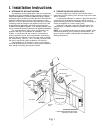
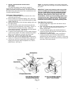
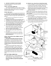
The exact placement of the various components of the
appliance will vary from installation to installation. The
installer, in conjunction with the customer, must decide on
where to place the faucet, tank and purification assembly by
balancing the homeowner's convenience with ease of installa-
tion and servicing. (See Fig. 1 & 7). A nearby electrical outlet
will also be required for proper installation of this device.
Considerations for an icemaker or other remote hookup
should be predetermined, including routing and any additional
tools, fittings, and tubing that may be required.
B. PREPARE THE AREA FOR INSTALLATION
Remove supplies from under the sink and stack them
neatly away from the working area. Arrange a light for the work
area, if necessary.
If a basement installation is called for, determine where the
components will be located and how they will be mounted.
Special mounting brackets and hardware may be necessary to
secure the appliance to a wall or ceiling joists.
Inspect the cold water supply line and determine if any
special fittings, in addition to what is included in the kit, are
required.
NOTE:
It is a good idea at this time to check the condition of the
undercounter plumbing for any existing or potential leaks. Any
items of concern should be repaired prior to installation of the
drinking water device.
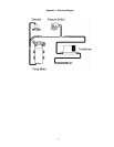
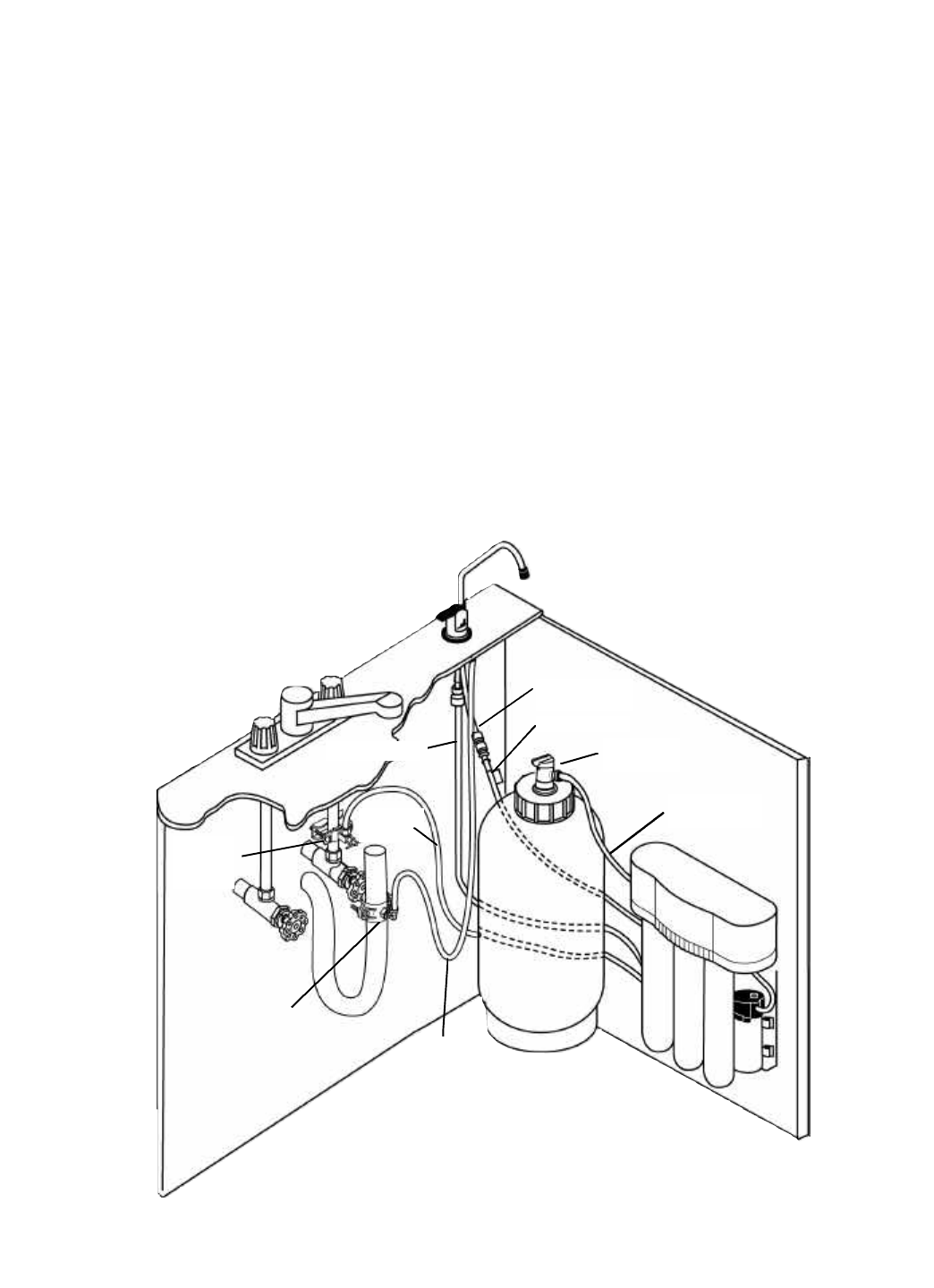
I. Installation Instructions
3
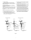
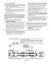
Fig. 1
Storage Tank
Drain Saddle
Feedwater
Tapping
Valve
1/4” Orange
Tubing
3/8” Black
Tubing
3/8” Blue Tubing
1/4” Green Tubing
Red SFC Tubing
Storage Tank
Valve
3/8” Yellow
Tubing
Sink Drain
Purification Assembly
* 110/60 (220/50) Electrical Connection
Necessary at This Location