


46
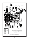
XI Wiring
WARNING
All wiring and grounding must be done in accordance with the authority having jurisdiction
or, in the absence of such requirements, with the National Electrical Code (ANSI/NFPA 70),
WARNING
Attempting to directly connect a low voltage thermostat and/or low voltage wiring to the orange
thermostat leads could cause property damage and/or create hazard of fi re or electricutuion.
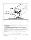
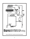
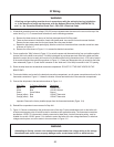
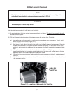
All electrical connections are line voltage (120 VAC) and are located under the cover on the cover on the top of the 1)
control box (Fig 11.1). To access these connections, use the following procedure:
Remove the three screws on the top of the front jacket panel and lift off the panel. a)
There are three screws in the bottom of each side jacket panel: two near the front and one near the back. b)
Remove the two screws near the front and loosen the screw near the back.
Spread the side jacket panels apart slightly, slide the control box forward and then rotate the control box down c)
as shown in Figure 11.1.
Remove the cover shown in Figure 11.1 to access the electrical connections. d)
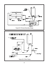
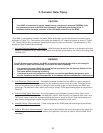
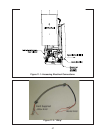
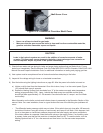
Crown supplies the “Whip” shown in Figure 11.2 to route the power and thermostat wiring from an installer supplied 2)
junction box into the boiler’s control box. This Whip is designed to provide proper strain relief at the boiler and also
permits the control box to be easily slid in and out of the boiler with all wiring connections intact. A 7/8 hole is located
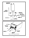
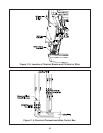
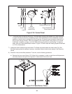
in the metal rail behind the control box as shown in Figure 11.3. Power and thermostat wiring is routed into the boiler
from underneath (Figure 11.5) and the BX connector on the “boiler end” of the Whip is secured in this 7/8” opening.
Route the whip leads into the electrical connection compartment. DO NOT CUT THE WHIP LEADS ON THE 3)
BOILER END.
Two terminal blocks are located in the electrical connection compartment: one for power connections and one for the 4)
thermostat connections. Figure 11.3 shows the location of these terminal blocks in the connection compartment.
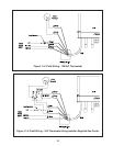
Connect the whip leads to the terminals as shown in Figure 11.4:5)
Whip Color To Factory Wire Color Description
Black Brown 120VAC “Hot”
White Blue 120 VAC Neutral
Green Green/Yellow Ground
Orange (either) Blue 120VAC Thermostat
Orange (either) Red 120VAC Thermostat
Important: Remove the factory installed jumper from the thermostat terminals (Figure 10.4)
Reinstall the compartment cover removed in Step #1d.6)
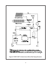
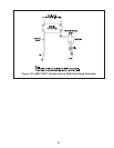
Figure 11.5 shows connections at the junction box end of the whip. Provide a dedicated circuit for the boiler with 7)
at least one emergency shut-off switch located in accordance with applicable codes. The thermostat connections
provided are 120VAC. If a thermostat is directly connected to these leads, it and all intervening wiring, must be
suitable for use with 120VAC power. If it is desired to control the boiler with a low voltage thermostat, or other low
voltage control system, use a fan center to do so as shown in Figure 11.6
and / or, the Canadian Electrical Code Part I ,CSA C22.1,Electrical Code.