


28
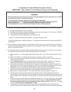
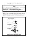
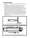
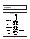
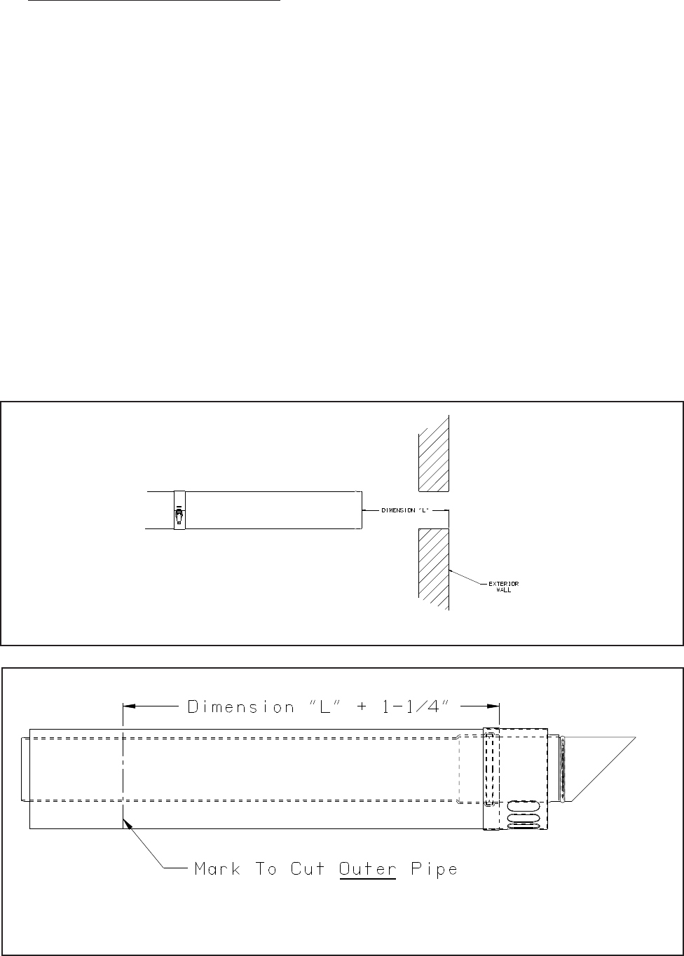
Figure 7.34a: Dimension “L”, 80/125mm Horizontal Terminal
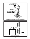
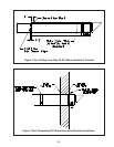
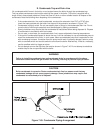
Figure 7.34b: Cutting Outer Pipe Of 80/125mm Horizontal Terminal
80/125mm Horizontal Terminal Installation5) -
Cut a 5-1/2” diameter hole through the exterior wall at the planned location of the horizontal terminal. a)
Measure distance “L” from the outside surface of the exterior wall to the end of the last fi tting as shown in b)
Figure 7.34a.
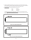
Add 1-1/4” to distance “L”. Carefully mark this length on the pipe as shown in Figure 7.34b.c)
Remove the inner pipe from the terminal, by gently pulling on it from the male end. Set aside.d)
Cut the e) outer pipe only at the point marked in Step (c) using aviation shears, a hacksaw, or an abrasive
wheel cutter. Be careful to cut the pipe square. De-burr the cut end with a fi le or Emory cloth.
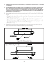
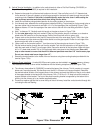
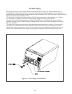
Reinstall the inner pipe in the terminal, making sure that the female end of this pipe is completely f)
bottomed out over the aluminum male connection visible behind the air intake grill. Place a mark on the
inner pipe 3/8” beyond the end of the outer pipe (Figure 7.34c). Use a fi ne tooth hacksaw to cut the pipe
and be careful to cut the pipe square (if necessary, the pipe can be removed from the terminal again for
cutting). De-burr the cut edge of the pipe with a fi le, razor blade, or fi ne sandpaper.
Make a mark on the terminal section 1” from the cut end of the outer pipe as shown in Figure 7.34c.g)
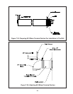
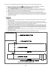
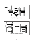
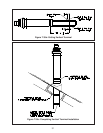
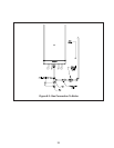
Slip the terminal section through the wall from the outside. Pass the terminal through the inner wall plate h)
and push into the last section of vent pipe until the mark made in Step (g) is not longer visible (Figure
7.34d). Secure the terminal to the last piece of pipe with three #10 x 1/2” sheet metal screws. Drill a 1/8
hole through both outer pipes to start these screws. Use a drill stop or other means to ensure that
the drill bit does not penetrate more than 3/8” into the outer pipe. Do not use a sheet metal screw
longer than 1/2”.
Slip the outer wall plate over the terminal and secure to the wall (Figure 7.34d). Apply a 1/8” bead of i)
weather resistant RTV over the joint between the outside wall plate and the terminal. Secure the other
wall plate to the inside wall.