


5
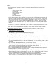
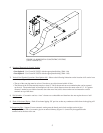
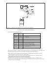
FIGURE 1.2: HORIZONTAL CONCENTRIC VENTING
(VENT OPTION 3,4)
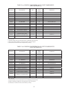
6) Permitted Terminals for Vertical Venting -
• Vent Option 8 - Use Crown PN 230532 with the appropriate fl ashing (Table 1.6a)
• Vent Option 9 - Use Crown PN 230570 with the appropriate fl ashing (Table 1.6b)
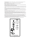
7) Vertical Vent Terminal Locations (Vent Options 8,9) - Observe the following limitations on the location of all vertical vent
terminals (see Figure
1.7):
• The top of the vent pipe must be at least 2 feet above any object located within 10 feet.
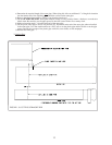
• The bottom of the air inlet terminal must be at least 12” above the normal snow accumulation that can be expected
on the roof. The terminal used in Vent Options 8 & 9 has a fi xed distance above the storm collar of 19”. If a greater
distance is needed to provide the clearance above the snow line, build a chase on the roof and mount the vertical
terminal on top of the chase.
8) Wall thimbles – Concentric vent has a “zero” clearance to combustibles and therefore does not require the use of wall
thimbles.
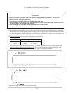
9) Pitch of Horizontal Piping - Pitch all horizontal piping 5/8” per foot so that any condensate which forms in the piping will
run towards the boiler:
10) Supporting Pipe - Support Crown concentric venting near the female end of each straight section of pipe.
Exception: Vertical runs of concentric pipe in an unused chimney (Figure 1.14) need only be supported at the
terminal and at the base of the run.