


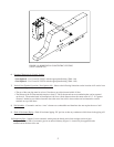
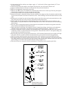
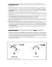
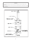
a) Start assembly of the vent system at the boiler. Lubricate the brown gasket in the boiler vent collar with a few drops
of water.
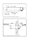
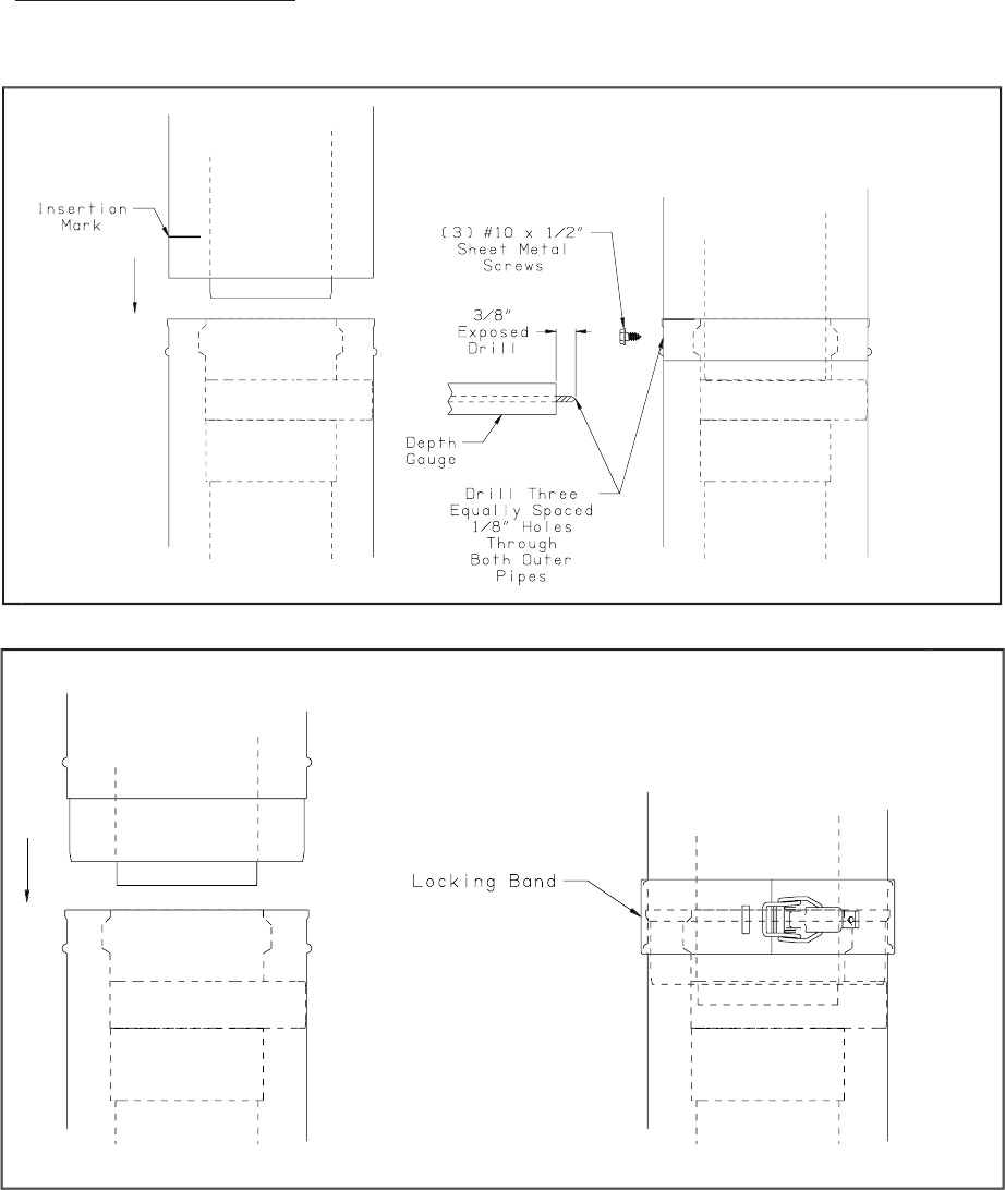
b) Push the male end of the fi rst fi tting into the boiler collar until it bottoms out. The male end of cuttable sections
should go 1” into the collar until the insertion mark (made in Step 2d above) is covered. On other fi ttings, the bead
on the male pipe will bottom out on the collar (Figure 1.11b).
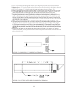
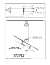
c) The male end of cuttable fi ttings must be held to the collar with three #10 x 1/2” sheet metal screws. Drill a 1/8 hole
through both outer pipes to start this screw. Use a drill stop or other means to ensure that the drill bit does not
penetrate more than 3/8” into the outer pipe. Do not use a sheet metal screw longer than 1/2” (Figure 1.11a).
d) Use locking bands (provided with all fi ttings) to secure non-cuttable pipe, as well as fi ttings, to the boiler collar
(Figure 1.11b).
e) Use the same method to join all remaining vent components except for the terminal.
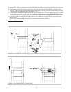
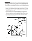
4) Horizontal Terminal Installation
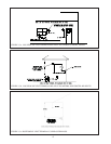
FIGURE 1.11a: JOINING CUTTABLE PIPE
FIGURE 1.11b: JOINING NON CUTTABLE PIPE
13