


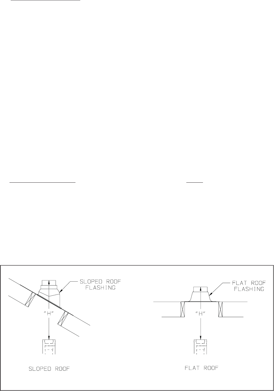
6) Vertical Terminal Installation - In addition to the vertical terminal, either a Flat Roof Flashing (80/125 PN
230533, 100/150 PN 230571) or Sloped Roof Flashing (80/125 PN 230535, 100/150 PN 230572) is required for
this installation.
a) Determine the center line of the terminal location on the roof. If the roof is fl at, cut a 5-1/2” diameter hole for
the 80/125 terminal and a 6-1/2” diameter hole for the 100/150 terminal. If the roof is sloped, cut a hole large
enough for the terminal to pass through the roof while remaining plumb. Caution: If the boiler is installed
directly under the hole, cover it while cutting the hole to prevent saw dust and other debris from falling
into the boiler.
b) Install the roof fl ashing using standard practice for the roofi ng system on the structure.
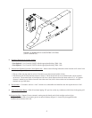
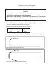
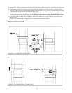
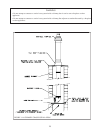
c) If not already done, assemble the venting system inside the building. The last section of pipe needs to be on the
same center line as the terminal and within 19-1/4” (80/125) or 28” (100/150) of the top edge of the roof fl ashing
(Figure 1.13a).
d) Measure distance “H” from the top edge of the storm collar to the end of the last fi tting as shown in Figure 1.13a.
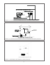
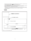
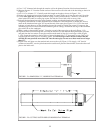
e) Add 1” to distance “H”. Carefully mark this length on the pipe as shown in Figure 1.13b.
f) Cut the outer pipe only at the point marked in Step (e) using aviation shears, a hacksaw, or an abrasive wheel
cutter. Be careful to cut the pipe square. De-burr the cut end with a fi le or emery cloth.
g) Place a mark on the aluminum inner pipe 3/8” beyond the end of the outer pipe (Figure 1.13b). Use a fi ne tooth
hacksaw to cut the aluminum pipe and be careful to cut the pipe square. De-burr the cut edge of the aluminum
pipe with a fi le or emery cloth.
h) Make a mark on the terminal section 1” from the cut end of the outer pipe as shown in Figure 1.13b.
i) Slip the terminal section through the roof from the outside. Push into the last section of vent pipe until the mark
made in Step (h) is not longer visible. Secure the terminal to the last piece of pipe with three #10 x 1/2” sheet
metal screws. Drill a 1/8” hole through both outer pipes to start these screws. Use a drill stop or other means
to ensure that the drill bit does not penetrate more than 3/8” into the outer pipe. Do not use a sheet metal
screw longer than 1/2”.
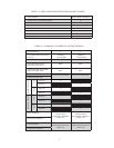
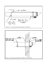
j) Secure the terminal section to the inside of the roof structure using the mounting bracket provided with the
terminal (Figure 1.13c).
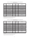
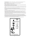
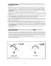
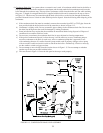
7) Chimney Chase Installation - A vertical vent system can be installed in an unused masonry chimney. This
installation is similar to other vertical installations with the following exceptions (Also see Figure 1.14):
a) The chimney chase elbow kit (80/125 PN230530, 100/150 PN 230568) is used at the base of the chimney. This
kit consists of a support elbow and a mounting bracket. Slip the elbow over the M10 x 35 screw in the support
bracket. Determine the desired vertical location of the support elbow in the chimney and mark the location of
the pin on the back of the support bracket on the back wall of the chimney. Drill a 7/16”dia x 2-1/2” deep hole
at this location to support the back of the bracket. The front of the elbow mounting bracket is supported by the
bottom of the opening into the chimney or by an installer supplied bracket.
b) Construct a weather-tight fl at roof to cover the top of the old chimney. Install the vertical terminal through this
roof using the fl at roof fl ashing.
16
FIGURE 1.13a: DIMENSION “H”