10
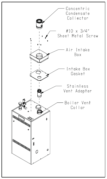
e) On the male end of the stainless vent adapter, apply a ¼” wide bead of silicone approximately 1/2” from
the end of the pipe.
f) Insert the male end of the stainless vent adapter into the boiler vent collar until it bottoms out.
g) Apply an additional bead of silicone over the outside of the joint and smooth out.
h) Replace and tighten the clamp on the vent collar.
i) Remove one (BWC150) or two (BWC225) of the #10 sheel metal screws on the top of the rear jacket panel
and place the air intake box over the vent and onto the boiler.
j) Use the exposed holes to line up the air intake box and gasket.
k) Insert the concentric condensate collector into the stainless vent adapter and the air intake box until the bead
on the collector bottoms out on the air intake box collar. Turn the fi tting so that the threaded stub faces to the
right.
l) Square up the air intake box and the foam rubber gasket to the boiler jacket and loosely attach the box to the
rear jacket panel with one of the previously removed #10 sheet metal screws.
m) Drill a single 1/8” hole through one of the mounting holes on the opposite side of the air intake box and
attach the box to the jacket with one of the #10 sheet metal screws. This will insure the rest of the mounting
holes line up.
n) Drill 1/8” holes in through the remaining mounting holes and attach the air intake box and gasket to the boiler
jacket with the remaining #10 sheet metal screws.
o) Apply pipe thread sealant tape (not supplied) to the 90° barbed hose fi ttings. Attach one to the condensate
collector adapter and the other to the bottom of the tapped condensate trap plug. (Figures 1.8, 1.15)
p) Attach the condensate collector adapter to the threaded portion of pipe sticking out the side of the concentric
condensate collector so that the hose barb is facing down. Slide one end of the 1/2” clear plastic tubing over
the hose barb and attach the hose clamp.
q) Run the tubing down the right side panel and into the 1-3/8” knockout located on the lower right of the right
side panel. Be sure to remove all burrs from the knockout to prevent the hose from being punctured.
r) Remove the plug and black gasket ring from the bottom of the condensate trap located under the boiler.
s) Reinstall the gasket ring onto the tapped condensate trap plug. Insert the tapped plug (which has the barbed
hose fi tting attached to it) in the base of the trap in place of the original plug. Slide the other end of the clear
plastic tubing over the hose barb and attach the hose clamp. (Figure 1.15)
t) Allow the silicone to cure per the silicone manufacturer’s instructions before operating the boiler.
FIGURE 1.8: CONCENTRIC VENT
ADAPTER ASSEMBLY


