


All installations and services must be performed by qualified service personnel.
7
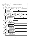
II. ECM TROUBLE SHOOTING
A. DIAGNOSTC FEATURES
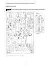
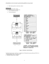
The control board is equipped with 4 green Input Status LEDs and 1 red Board Status LED. These are intended to
provide a quick view into furnace performance without requiring a voltmeter.
The green Input Status LEDs are driven by the “Y”, “W”, “G”, and “DEHUM” inputs and are located directly
below those inputs. They will light to indicate the presence of these signals.
The red Board Status LED has two functions:
It will light when the board recognizes a valid input signal and will stay lit until all valid signals are removed.
This is intended to show that the board is functioning and able to respond to input signals.
It will flash rapidly while120VAC is missing from the LIMIT switch. This is intended to give a quick visual
indication of the High LIMIT switch.
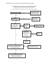
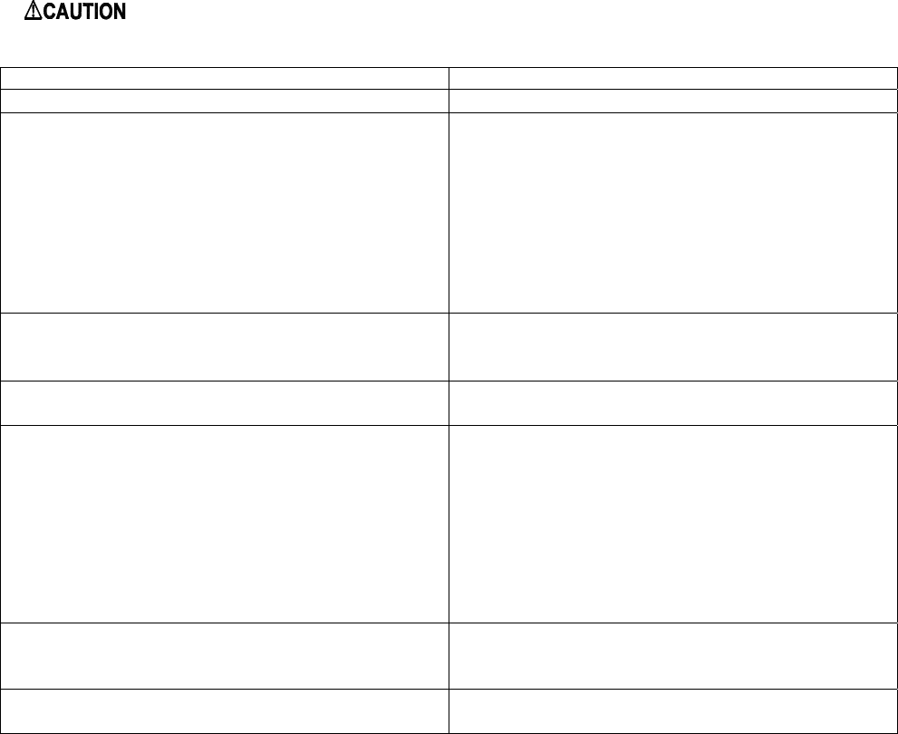
B. GENERAL GUIDELINES TO TROUBLESHOOTING GE ECM – DRIVEN SYSTEMS
: Disconnect power from unit before removing or replacing connectors, or servicing motor.
Wait at least 2 minutes after disconnecting power before opening motor.
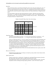
SYMPTOM CAUSE/PROCEDURE
Motor rocks slightly when starting
• This is normal start-up for ECM
Motor won’t start
• No movement
• Check power at motor
• Check low voltage (24 VAC R to C) at motor
• Check low voltage connections
(G,PWM,W,R,C,) at motor
• Check for unseated pins in connectors on motor
harness
• Test with a temporary jumper between R – G
• Check motor for tight shaft
• Run Moisture Check
• Motor rocks, but won’t start • Check for loose or compliant motor mount
• Make sure blower wheel is tight on shaft
• Perform motor/control replacement check
Motor oscillates up & down while being tested off
of blower
• It is normal for motor to oscillate with no load on
shaft.
Motor starts, but runs erratically
• Varies up and down or intermittent
• Check line voltage for variation or “sag”
• Check low voltage connections
(G,PWM,W,R,C,) at motor, unseated pins in
motor harness connectors
• Check “Bk” for erratic CFM command (in
variable speed applications)
• Check-out system controls – T’stat?
• Perform Moisture Check
• “Hunts” or “puffs” at high CFM (speed) • Does removing panel or filter reduce “puffing”?
Reduce restriction
Reduce max airflow
• Stays at low CFM despite system call for cool or
heat CFM
• Check low voltage (T’stat) wires and connections