


All installations and services must be performed by qualified service personnel.
4
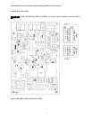
EAC (electronic air cleaner)
The control provides a 120VAC output for an electronic air Cleaner. This output is energized whenever the fan
motor is energized (either low, heat or cool speed). Connection is made via male quick connect terminal
labeled "EAC".
Humidifier
The control provides a 120 VAC output for a humidifier. Connections are made to a male quick connect
terminal labeled "EAC". In this application, the humidifier will operate on any blower operation. Humidifier
should be controlled by humidistat to prevent operation during cooling fan operation.
Status LED
A red LED is provided to indicate any thermostat input has been recognized by the microprocessor on the
control. See Diagnostic Features for a function description of operation.
Thermostat Input LEDs
Four green LEDs are placed beneath their respective thermostat connections (W, Y, G and DEHUM) and
operate whenever a call is present. See Diagnostic Features for a function description of operation.
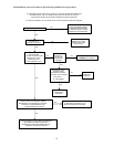
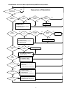
E. Operating Modes
Standby Mode
All outputs are off and the control is waiting for a thermostat demand. The thermostat inputs, and limit switch
are continuously monitored. The control initiates action when a thermostat call is received or limit switch
opens.
Fan Mode
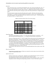
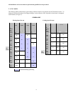
A call for fan ("G") is received from the thermostat. If no other mode is calling for blower operation, the
control will choose a “Low” speed value from the position of DIP switch SW1 positions 4 through 6, as
shown in the CFM Tables. and operate the fan at that speed. The fan mode will be operated as long as the
"G" input is calling and neither the Heat mode nor the Cool mode is calling for blower operation. When the
Heat and Cool modes call for blower operation, their respective outputs will take over after their respective
turn-on time delays have expired. The speed Output is present until the fan call is satisfied.
Cooling Mode
A call for cool ("Y") is received from the thermostat. If the heat mode is not active or the anti-short cycle delay
is not in effect, the control will energize the “CC” terminal. After a 10 second delay ramps up to the “COOL”
speed determined by the position of DIP switch SW1 (positions 4 through 6) determine a speed as shown in
CFM Tables.
When the call for cool is satisfied, the “CC” terminal is de-energized and the cooling off delay of 45 seconds is
started. Forty-five seconds later the blower speed ramps toward zero and the control reverts to Standby Mode.
Dehumidification Operation
If a call for dehumidification is received while the Cool Mode is active, blower speeds will be reduced.
The speed value will be selected from the LOW column of the CFM Tables.
Anti-Short Cycle Operation
To prevent compressor short cycling, a call for cooling will be ignored for four minutes after the
termination of any cooling call. The anti-short cycle delay is also in effect at power-up.