


All installations and services must be performed by qualified service personnel.
1
I. BLOWER CONTROLLER INFORMATION
A. TERMINAL DEFINITIONS & FIELD WIRING
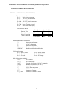
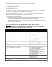
Burner Harness Connector P1
Pin 1 – Limit switch connection.
Pin 2 – 120 VAC Line connection.
Pin 3 – Burner pilot contact.
Pin 4&5 – 120 VAC Neutral connection.
Pin 6 – Burner pilot contact.
Pin 7&8 – From oil primary control.
Pin 9 – Limit Switch Input (LSI).
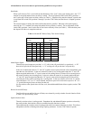
Field Wiring to Burner
Pilot (Tstat) Neutral Line
Yellow Wires
White Red
T-T terminals
White Black
T-stat terminals
White Black
Harness Wires
Beckett Connections
Riello Connections
Carlin Connections
T-T terminals
White Black
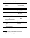
Thermostat/Humidistat connections
"C" Common/ground
"W" Thermostat call for heat
"R" 24 VAC to thermostat
"G" Thermostat call for fan
"Y" Thermostat call for cool
“DEHUM” Humidistat call for dehumidification
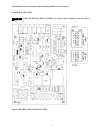
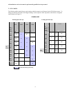
ECM control outputs
Pin 1 - Speed Common Pin 4 – Blower Enable
Pin 2 - Speed Output Pin 5 – COOL Enable
Pin 3 - Not used. Pin 6 – “R” Output
Male quick connect terminals.
"S1-3” 120 VAC Hot
“N1-7” 120 VAC Neutral
“EAC” Electronic Air Cleaner (120 VAC) connection.
“HUM” Humidifier connection (120 VAC).
"FAN" Fan On Signal
“X” 24VAC from transformer.
“C” 24VAC common from transformer.
"CC" Compressor Contactor
"CC_COM" Compressor Contactor Common