


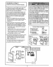

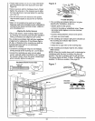
Installation Step 10 " ---]
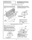
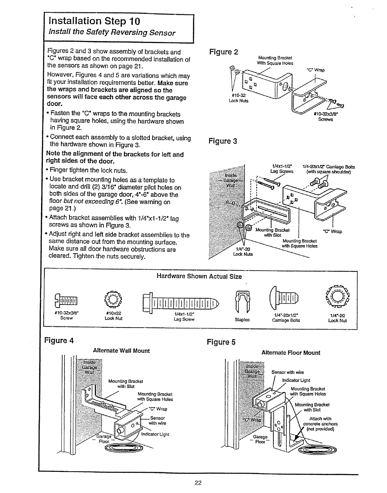
Figures 2 and 3 show assembly of brackets and
"C" wrap based on the recommended installation of
the sensors as shown on page 21.
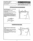
However, Figures 4 and 5 are variations which may
rr_your installation requirements better° Make sure
the wraps and brackets are aligned so the
sensors will face each other across the garage
door.
° Fasten the "C" wraps to the mounting brackets
ha,.4ng square holes, using the hardware shown
in Figure 2.
• Connect each assembly to a slotted bracket, using
the hardware shown in Figure 3o
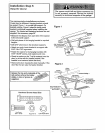
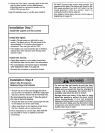
Note the alignment of the brackets for teft and
right sides of the door.
• Finger tighten the lock nuts.
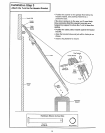
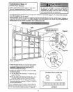
° Use bracket mounting holes as a template to
locate and ddH (2) 3/16" diameter pilot holes on
both sides of the garage door, 4"-6" above the
floor but not exceeding 6; (See warning on
page 21 ,)
• Attach bracket assemblies with 1!4"x1-1/2" lag
screws as shown in Figure 3.
• Adjust right and left side bracket assemblies to the
same distance out from the mounting surface.
Make sure all door hardware obstructions are
cleared. Tighten the nuts securely.
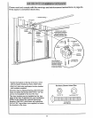
Figure 2
Meurrdng BracJ_t
W'_ Square Hoes
114"-20
LockNtr_.s
Figure 3
©
#10-32.x3/8 ° #10x_2
Screw LockNut
Hardware Shown Actual Size
1/4"-20*zif2 ° 1/4"÷20
LagScrew S_tes Cania_e BOILS LockNut
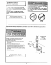
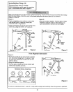
Figure 4
Alternate Wall Mount
Figure 5
A|temate Roor Mount
Sensorwithw_re
In_calor IJght
Mounting Bracket
wiLhSquareHoles
Mount_g Bracket
with Stot
Attach wiLh
¢onc_ele anchors
(net provided)
22