


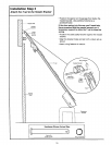
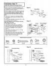
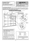
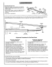
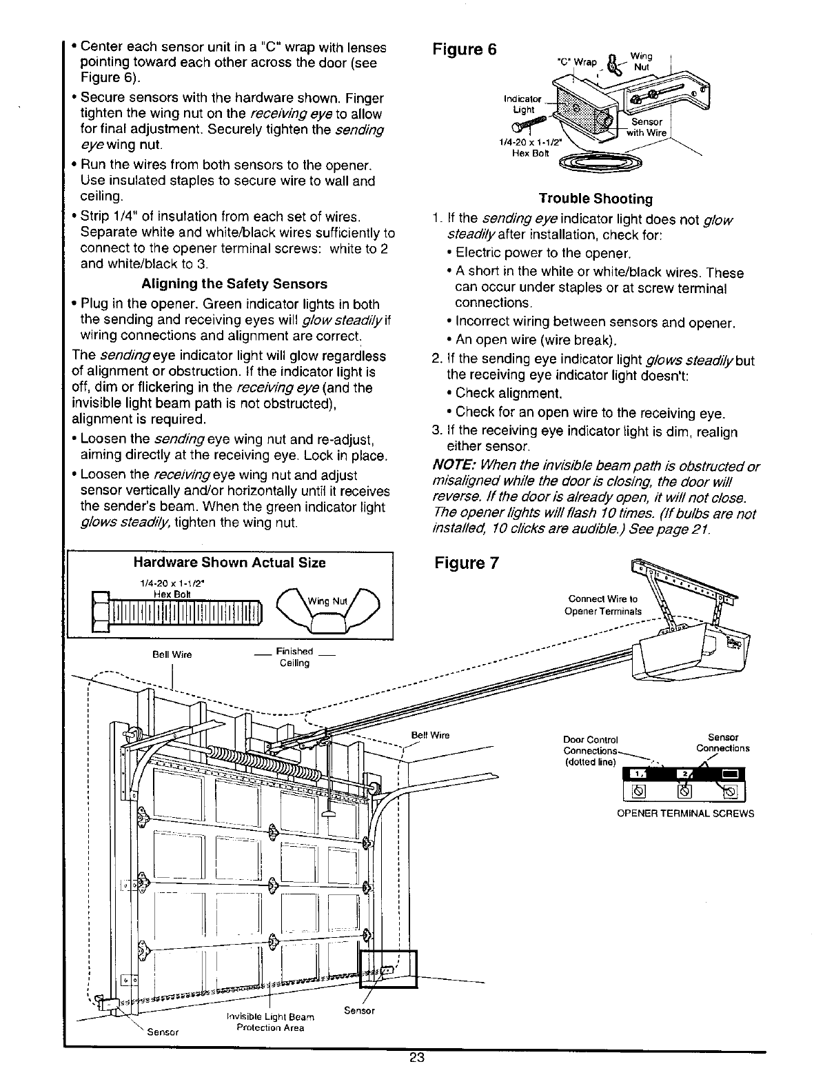
• Center each sensor unit in a "C" wrap with lenses
pointing toward each other across the door (see
Figure 6).
• Secure sensors with the hardware shown. Finger
tighten the wing nut on the receiving eye to allow
for final adjustment. Securely tighten the sending
eye wing nut.
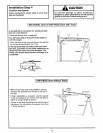
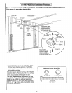
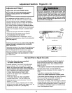
• Run the wires from both sensors to the opener.
Use insulated staples to secure wire to wall and
ceiling.
• Strip 1/4" of insutation from each set of wires.
Separate white and white/black wires sufficiently to
connect to the opener terminal screws: white to 2
and white/black to 3.
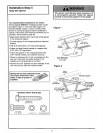
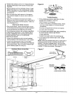
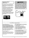
Aligning the Safety Sensors
• Plug in the opener. Green indicator lights in both
the sending and receiving eyes will g/owstead#yif
wiring connections and alignment are correct:
The sendingeye indicator light will glow regardless
of alignment or obstruction, if the indicator light is
off, dim or flickering in the receiving eye (and the
invisible light beam path is not obstructed),
alignment is required.
• Loosen the sendingeye wing nut and re-adjust,
aiming directly at the receiving eye. Lock in place.
• Loosen the receivlngeye wing nut and adjust
sensor vertically and/or horizontally until it receives
the sender's beam. When the green indicator light
glows stead#y, tighten the wing nut.
Figure 6
"C" Wra
Indicator
Light
1/4-20 x 1-1/2"
Hex Bo_
Trouble Shooting
1. If the sending eye indicator light does not glow
steadily after installation, check for:
• Electric power to the opener.
• A short in the white or white/black wires. These
can occur under staples or at screw terminal
connections.
• Incorrect wiring between sensors and opener.
• An open wire (wire break).
2. If the sending eye indicator light glows steadi/ybut
the receiving eye indicator light doesn't:
• Check alignment.
• Check for an open wire to the receiving eye.
3. If the receiving eye indicator light is dim, realign
either sensor.
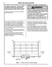
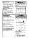
NOTE: When the invisible beam path is obstructed or
misaligned while the door is closing, the door will
reverse. If the door is already open, it will not close.
The opener lights will flash 10 times. (if bu/bs are not
installed, 10 clicks are audible.) See page 21.
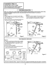
Hardware Shown Actual Size
1/4-20 x 1-1/2"
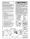
Figure 7
Bell Wire __ Finished __
Bell Wire
Connect Wire to
Opener Terrninals
Door Control Sensor
Conneciions_ Connections
(dotted line) -'- 7
[]
OPENER TERMINAL SCREWS
Invisible Light Seam
Sensor Protection Area
Sensor
23