Assembly Step 4
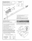
Install the Chain/Cab@ &
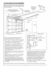
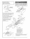
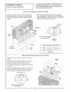
Attach the Sprocket Cover
Figure 2 o_
_OCkef
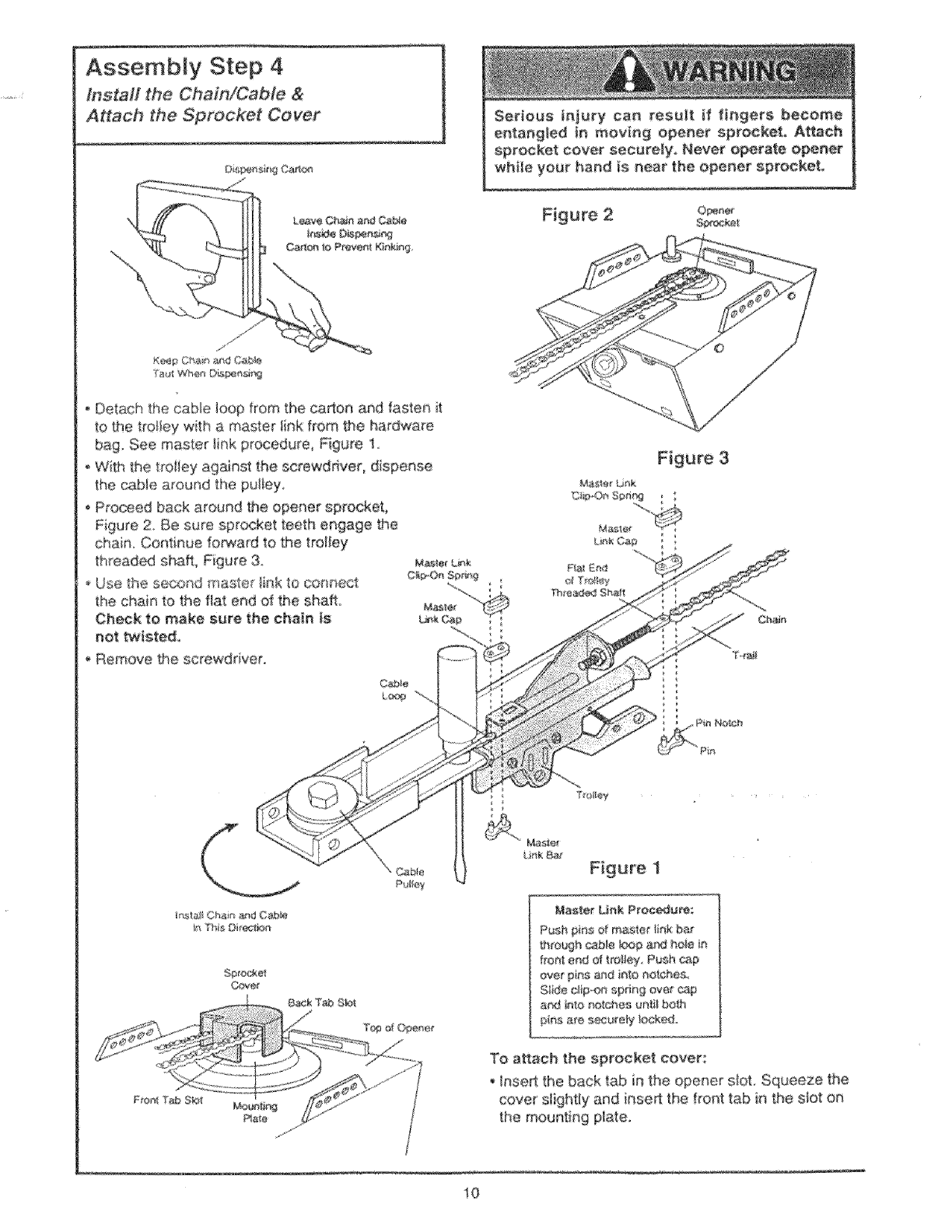
Detach the came loop from the capon and fasten it
to the tro!fey with a master link from #Behardware
bag See master link procedure, Figure 'I,
WiSh the trolley against the serewdnvec dispense
the c_>_e around the pu_tey,
, Pro@_edback around the opener sprockeL
Figure 2. Be sure sprocket teeth engage t}he
chain, Continue forward to the trolley
thresd_ shaft, Figure 3.
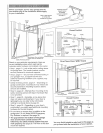
Use the se_:md master _nk to connect
the chain to the flat end of the shaft.
Check to make sure the chain is
not twtsted,
, Remove the screwdriver
F_gure 3
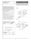
Ma$_er Unk
n The Oit_a
Master LJ_k Pr_r_;
P_sh pins of r_3_stet link bar
through _b_e k_p a_ hole in
#on_ end d t_liey, Push _p
over pins_nd into risk;hoe
Stag c_po_ spdng over_ep
a_ into _yotchee unti_ _t_h
pins are s_ure_y i_kedo
To a_ach the sprocket cover:
InseA the back t_ inthe opener sbt. Squeeze the
cover slightly and inseA the front tab in the s/st on
the mounting plate,
10


