


HEVK-5 5’ VENT EXHAUST KIT
INSTALLATION INSTRUCTIONS
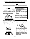
WARNING: Use only Louisville Tin & Stove Company factory supplied parts and kits. Failure to do so could result in
loss of life, personal injury, property damage, or unsatisfactory performance.
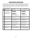
CONTENTS OF KIT
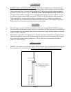
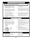
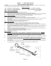
1 only P/N 72532 2”x3” Steel Coupling 1 only P/N 41520 Center Bracket
1 only P/N 72575 2”x5’ Black Flocked Tube 8 only P/N 72593 2” Hose Clamps
1 only P/N 72612 2”x6’ Black Flex Tubing 1 only P/N 72578 2”x3” Black Silicone
2 only P/N 41515 Support Brackets Wrapped Coupling
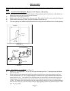
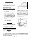
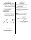
STEP 1 - LOCATE VENT OPENING
a) Select location on outside wall that vent will exit through.
b) Check outside for proper clearances around vent cap. See installation instructions.
c) Mark and cut 3-1/2” hole through both inside and outside walls, being sure to maintain level across both openings.
d) Measure wall thickness. Mark and cut off both intake and exhaust pipes to 1/2” beyond outside wall.
e) Secure collection box to wall. Wall anchors, not provided, may be required.
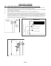
STEP 2 - INSTALL HEATER
a) Select location on wall where heater will be installed.
b) Using wall template supplied with heater, mark location for trim kit wall brackets.
c) Attach brackets to wall (wall anchors, not provided may be required) and back of heater. Using screws provided on
back of heater.
d) Slide heater into position and secure brackets togehter. This should position back of heater 5” off wall.
e) Select direction vent will exit trim kit, left, right, or straight up.
f) Before installing trim kit remove knockout on this side.
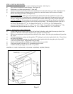
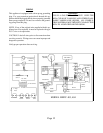
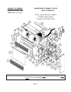
STEP 3 - INSTALL VENT
a) Remove and discard P/N 72611 2”x24” black flex tubing from air inlet. (Save hose clamp).
b) Attach P/N 72612 2”x6’ black flex tubing to air inlet. Secure with P/N 72593 2” hose clamp.
c) Slide P/N 72575 2”x5’ flocked tube through trim kit opening (knockout) and attach to P/N 72610 orange silicone
90- elbow supplied with heater. Secure with 2” hose clamp.
d) Attach P/N 41515 support brackets to wall. Wall anchors, not provided, may be required. Postion support brackets
within 8” from side of trim kit and end of pipe. Secure flex tubing and flocked tube to brackets using 2” hose
clamps.
e) Attach P/N 41520 center bracket 2-1/2’ from pipe end and insert flex tube through bracket. This will prevent the
flex tube from touching the black flocked exhaust tube.
f) Connect flex air intake tube and flocked exhaust tube to collection box.
g) Complete gas connection and attach trim kit to brackets.
h) Follow lighting instructions.
SPECIAL NOTES
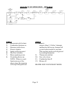
a) You may use up to three HEVK-5 Kits for a total of 15’ vent extension with two additional elbows. DO NOT
EXTEND VENT BEYOND 15’ OR USE MORE THAN THREE TOTAL ELBOWS (one elbow is attached to
heater outlet).
b) To connect two vent kits together use P/N 72532 2”x3” steel coupling. Secure with 2” hose clamps.
c) If you are using one, two, or three kits, after installation is complete you will discard 2 P/N 72593 hose clamps and
one P/N 72532 steel coupling.
d) If you need to make a 90- offset you will need to order P/N HEEL-1 90- Elbow Kit. Two offsets require two kits.
e) If complete vent extension is horizontal, pipes may be sloped down slightly to allow any condensate to
drain through the exhaust pipe to the outside. DO NOT ALLOW TO DRAIN ONTO WALKWAY. If any part of
vent extension is vertical or local codes do not allow draining of condensate to outside you must add P/N HECK-1
Condensate Kit.
f) For cosmetic purposes, the addition of the HEVK-5 Kit can be enclosed by adding a HEVE-5 Vent Enclosure Kit.
To completely enclose the HEVK-5 Kit one HEVE-5 will be needed for each HEVK-5 used.
Page 14
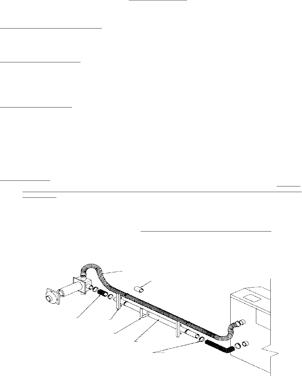
P/N 72612
2”x6’ Black
Flex Tubing
P/N 72532
Use only if connecting
flex tubing of 2 or
more ktis
P/N 72575 2”x5’
Black Flocked Tube
P/N 72593
2” Hose Clamps
P/N 41515
Support
Brackets (2)
P/N 72578 2”x3”
Black Silicone
Wrapped Coupling
P/N 41520
Center Bracket