


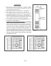
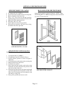

LOCATE VENT OPENING
After the location of the heater has been determined, the
opening for the vent pipe should be cut. If the heater is to be
recessed, cut out opening for heater between studs on the
interior wall and cut out the floor plate between the studs, so
heater will set flat on floor as all dimensions are given from
a finished floor. The height of the cut out for a 40,000 BTU
model is 78-5/8”, for the 55,000 and 62,500 models the cut
out height is 87-5/16”. NOTE: This dimension may be
increased to allow more room for installation and making
the wiring connection, then refinished.
Next, cut out a 9-1/4” opening in exterior wall for the vent
tubes to pass through. The center of opening for the 40,000
BTU furnace is 59”, the center for opening for 55,000 and
62,500 BTU furnaces is 68-1/2”. See Figure 5, on Page 6.
If the heater is to be surfaced mounted, cut out 9-1/4” opening
through the interior and exterior wall. The center of cut out
will be 59” for 40,000 BTU and 68-1/2” for 55,000 and
62,500 BTU models. Be sure both cutouts are level with
each other.
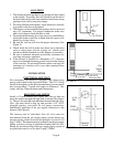
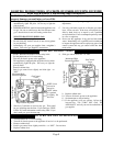
INSTALLING THE FURNACE
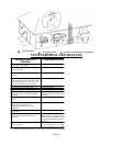
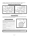
The vent system supplied with this furnace will accommodate
walls ¾” (when recessed) up to 12” thick. Use only the
exhaust tube, air intake tube and vent cap supplied with
heater. Do not attempt to lengthen the exhaust or air intake
tubes, this could cause an imbalance in the heater resulting
in poor performance and pilot outage (See Figure 6).
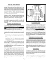
Measure exact distance “X” between surface on which back
of cabinet will rest (inside of recessed cavity or face of wall
when freestanding) and the outside wall surface (see Figure
6).
Inlet Air Tube “A” – Measuring from gasketed surface,
mark and cut pipe same as dimension “X”. Remove any
burrs.
Vent Exhaust Tube “B” – Measuring from gasketed
surface, mark and cut pipe 1-3/4” greater than dimension
“X”. Remove any burrs.
Fasten vent exhaust tube “B” to heat exchanger collar and
Inlet Air Tube “A” to flange on back of furnace using 16 #
3/8 screws (“C”) provided. Be sure gaskets are in place and
not damaged. Anytime the vent pipes are removed check
and replace gaskets (if necessary). Failure to replace missing
or damaged gaskets may expose homeowner to life
threatening conditions.
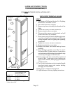
Secure furnace in place using 2 holes provided in bottom of
casing. NOTE: Make sure both tubes are centered in cut
out. Slide the vent cap onto the pipes extending from the
back of the furnace. A rotating or twisting motion will ease
this installation. Secure vent cap and vent cap spacer plate
to wall causing the vent tubes to have a slight downward
pitch. This will prevent water from entering. Anchors (not
provided) may be required. Caulk around vent cap spacer
plate with caulking provided. NOTE: Some framing may
be necessary to provide a flat surface against the vent cap
spacer plate and to prevent rain from entering the wall
opening.
GAS CONNECTION
Make the gas connection between the manual shut off valve
and the furnace gas control valve with approved ½”
connectors. Compounds used on threaded joints of gas
piping shall be approved for use with L.P. gas. The gas
lines must be checked for leaks by the installer with soapy
water or liquid detergent, never use an open flame. If
connections are not exposed, a pressure test must be run.
Be sure to disconnect the gas supply line from the appliance
valve before pressure testing. The manifold pressure is
pre-set at the factory and should be 3.5” w.c. for Natural
Gas and 10” w.c. for L.P. Gas. The minimum inlet pressure
for Natural Gas is 4.5” w.c. and 11” w.c. for L.P. Gas, “for
purpose of input adjustment”. The maximum inlet pressure
should never exceed 7.0” w.c. on Natural Gas or 14” w.c.
on L.P. Gas.
THERMOSTAT INSTALLATION
Follow the instructions included with the thermostat. Select
a location for the thermostat on an inside wall approximately
5 feet above the floor where it won’t be affected by heat or
cold sources such as direct sunlight, televisions, fireplaces,
hidden hot or cold water pipes, drafts, etc., and a minimum
of 4’ from the heater. The thermostat must never be placed
in an adjacent room. Connect thermostat wires to
thermostat and mount to wall. Run wire to furnace and
make connections to thermostat wires coming out of top of
furnace. Use insulated staples (provided) to secure wire to
wall.
OPERATION
This unit uses a “step action” valve. When the heater comes
on initially, it operates at a lower pressure to insure proper,
quiet, ignition. After 20 seconds or less, it automatically
steps up to the proper manifold pressure with a discernable
increase in flame height.
After the heat exchanger has warmed sufficiently, the fan
will automatically come on to efficiently transfer the heat
into the room. NOTE: All but the 40,000 BTU unit (which
is one-speed) have an automatic two-speed fan.
Vent
Cap
Vent Cap
Spacer
Plate
Heat
Exchanger
Collar
FIGURE 6
Page 7