


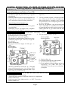
LOCATIONS
1. This furnace must be installed on an outside wall and vented
to the outside. If possible, this wall should be on the side of
the house that receives the least amount of wind since strong
gusting winds could cause pilot outage.
2. For most efficient performance, locate furnace as centrally
as possible in the area to be heated.
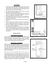
3. The furnace can be installed flush against a wall or recessed
up to 10” maximum. For proper combustion, make sure
unit is level front to back and side-to-side.
4. Do not install the furnace in a closet, alcove or small hallway
where the furnace could be isolated from the space to be
heated by closing a door.
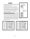
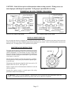
5. Be sure the vent cap will have the proper clearances (See
Figure 2).
6. Check inside the wall to make sure there are no obstacles
such as water pipes, electric wiring, etc. which could
interfere with the installation of the furnace or vent tubes.
7. Be sure to maintain adequate accessibility clearances for
servicing and proper operation.
8. If the furnace is installed in a basement, a 12” clearance
must be maintained between ground level and the bottom
of the vent cap. Do not install furnace where vent cap will
terminate in a window well or any other opening below
ground level.
INSTALLATION
ELECTRICAL ROUGH-IN
For convenience, this furnace is equipped with a three-prong
power cord located on the top left of heater. The 115V wiring
should be brought in on the left side terminating in a receptacle
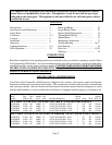
box (not provided). Consult local codes or ordinances. (For
Amps, see Page 2/Specifications and Dimensions).
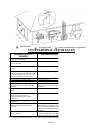
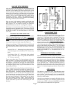
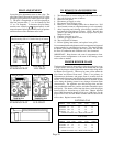
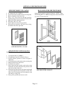
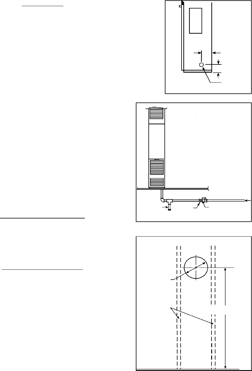
ROUGH-IN GAS SUPPLY
Install a 1/2 inch diameter gas supply line. The gas line can
enter the cabinet through the right side or bottom (See Figure
3). The gas line must have an individual manual shut off valve.
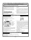
Also, you must install a drip leg and provide a 1/8” N.P.T.
plugged tapping, accessible for test gauge connection,
immediately upstream of the gas supply connection to the
furnace (See Figure 4).
The furnace and its individual shut off valve must be
disconnected from the gas supply piping system during any
pressure testing of that system at test pressures in excess of ½
psig (3.5kPa). The furnace must be isolated from the gas supply
piping system by closing its individual manual shut off valve
during any pressure testing of the gas supply piping system at
test pressures equal to or less than ½ psig (3.5kPa).
3-1/2”
2-5/8”
1-1/2 OA
FIGURE 3
Gas
Supply
Line
Drip
Leg
Manual
Cut Off
Valve
1/8 N.P.T.
Pressure Tap
FIGURE 4
Page 6
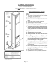
FIGURE 5
9-1/4
DIA.
WALL
STUDS
DVCF40 - 59”
DVCF55/65 - 68-1/2”
FINISHED
FLOOR