


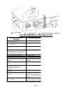
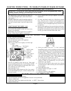
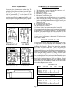
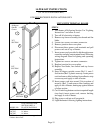

PILOT ADJUSTMENT
Locate the pilot adjustment screw on the valve. The
pilot flame should surround at least the top 3/8” of the
powerpile (pilot generator) or flame sensor (see Figure
7). The pilot is unregulated so it will be operating at
inlet line pressure (Max. 7” w.c. for Natural Gas and
11” w.c. for Propane). To decrease the pilot flame,
turn the screw clockwise (approximately six full
turns to bottom of pilot light channel) until you produce
sufficient flame at the minimum noise level.
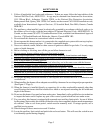
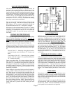
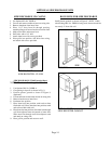
TO REMOVE MAIN BURNER FOR
INSPECTION AND CLEANING
1. Turn thermostat to lowest setting and allow furnace to cool.
2. Turn off all electric power to furnace.
3. Remove lower grille.
4. Disconnect gas supply to valve.
5. Disconnect wires from gas valve.
6. Remove 15 screws holding burner door to burner box. Pull
door forward to remove complete burner, gas valve assembly.
7. After inspecting and cleaning, place burner assembly back
into burner box and tighten 15 screws. NOTE: Be sure door
gasket is not damaged and will effect a proper seal or pilot
outage will occur.
8. Connect wires back to valve.
9. Connect gas supply back to valve.
10. Turn on electric to furnace.
11. Follow lighting instructions, and replace lower grille.
It is recommended that the furnace and all components be inspected
at least annually by a qualified service person. This should include
the burner, pilot, heat exchanger, and vent system. Be sure that
the flow of combustion and ventilation air is not obstructed.
IMPORTANT: Keep burner and control compartment clean.
Vacuum control compartment at the start of the heating season
and as often as needed.
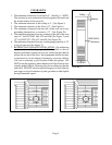
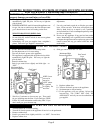
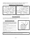
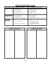
PROPER BURNER FLAME
The burner flame may be observed by raising the sight glass cover.
A proper flame will have a dark blue inner mantle that sits right
on top of the burners with a lighter blue outer mantle rising above
the burner (See Figure 8). There may be some yellow where the
pilot flame and burner flame meet. There is no primary air
adjustment on the burner, and proper flame is assured since the
correct manifold pressure and orificing has been done at the factory.
NOTE: It is advised that the burner flames be checked at least
twice during the heating season for any changes in burner flame
characteristics. The appliance area must be kept clear and free
from combustible materials, gasoline, and other flammable vapors
and liquids. This heater comes from the factory with the proper
burner orifice for elevations up to 2,000 feet. Heaters installed
above 2,000 feet must be derated 4% for every 1,000 feet. For the
proper orifice size, find the Model Number and elevation on the
orifice chart. Replace burner orifice.
PILOT FLAME ADJUSTMENT: Pilot flame
should envelop 3/8 to 1/2 inch of the tip of sensor.
3/8” to 1/2”
3/8”
to
1/2”
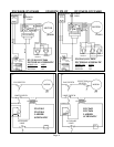
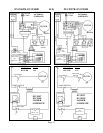
FIGURE 7A FIGURE 7B
STANDING PILOT I.I.D. PILOT
Pilot Adj. Screw
Pilot Adj. Screw
ROBERTSHAW
7200ER-SO4
ROBERTSHAW
7200IPER-SO4
FIGURE 7C FIGURE 7D
STANDING PILOT I.I.D. PILOT
1-1/
2
3/4
FIGURE 8
Page 10
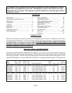
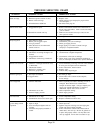
NATURAL GAS
MODEL 0 to 2,000 - 4,000 - 6,000 - 8,000 –
NUMBER 2,000’ 4,000’ 6,000’ 8,000’ 10,000’
DVCF403B 32 34 35 36 40
DVCF407B 32 34 35 36 40
DVCF557B 3.6m 29 30 30 31
DVCF653B 25 27 28 29 30
ORDER KIT #49840 2287-1 HIGH ALTITUDE KIT
L.P. GAS
MODEL 0 to 2,000 - 4,000 - 6,000 - 8,000 –
NUMBER 2,000’ 4,000’ 6,000’ 8,000’ 10,000’
DVCF404B 49 50 51 52 52
DVCF408B 49 50 51 52 52
DVCF558B 44 45 47 48 49
DVCF654B 2.3mm 44 45 47 48
ORDER KIT #49840 2287-1 HIGH ALTITUDE KIT