


14-PEK KIT INSTRUCTIONS
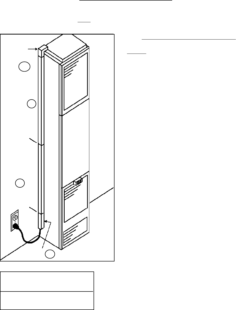
(14’ PLUG EXTENSION KIT)
FOR NON-RECESSED INSTALLATIONS ONLY
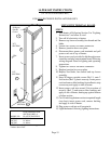
90 Degree
Outside
Corner
3 FT.
SECTION
WALL
3 FT.
SECTION
BOTTOM
SECTION
1
2
3
4
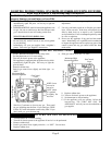
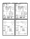
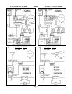
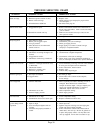
UNITS WITH TERMINAL BOARD
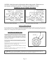
STEP #
1. Turn heater off following Section 3 in “Lighting
Instructions” and allow to cool.
2. Turn off all electricity to heater.
3. Remove top louver assembly, fan shroud and fan
blade.
4. Loosen two screws on romex connector.
5. Remove junction box cover plate.
6. Disconnect three power cord terminals and pull
power cord out of top of heater.
7. Insert power cord provided in kit through romex
connector and plug onto terminal board following
wiring diagram found in lighting and operating
instructions.
8. Tighten two screws on romex connector.
9. Replace junction box cover plate.
10. Replace fan blade, fan shroud and top louver
assembly.
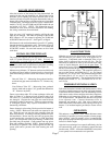
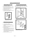
11. Snap 90 degree outside corner (Ref. 1) onto 3
foot section (Ref. 2) plastic raceway. Insert power
cord and remove blue backing from adhesive strip
on raceway and apply to side of heater.
12. Insert power cord into second 3-foot section of
raceway (Ref. 3) and remove blue backing and
apply to side of heater, butting up against bottom
of other section.
13. Cut 14-inch long bottom section to required length
(see chart), insert power cord, remove backing
and apply to side of heater.
14. Plug power cord into wall receptacle.
15. Light the heater following lighting instructions.
Page 15
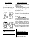
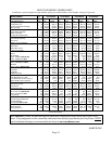
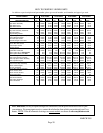
LENGTH OF BOTTOM
SECTION (REF. 4)
MODEL NO. PLASTIC RACEWAY
DVCF40 5-5/16 Inches
DVCF55 14 Inches
DVCF65 14 Inches
NOTE: Above lengths terminate approximately
2 inches above floor.