


5
ENGLISH
Regent light fixture. If not, Proceed to step 9. NOTE:
Quick connectors can only be used with solid wire
supply leads.
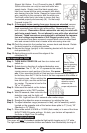
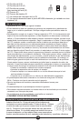
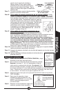
Simply insert the black supply wire
from your house into the quick connector with black
wire coming from the fixture. Repeat for house white
wire, matching to the connector with the white wire.
Push both wires firmly into holes to insure that they
are seated properly and securely (N). It’s that easy!
Proceed to step 10.
Step 9: If the supply wires coming from your house are stranded, remove
the quick connectors from the end of the light fixture wires by turning
them repeatedly from left to right while pulling. Repeat until they are
both removed.
Remember: Quick connectors can only be used with
solid wire supply leads.
Do not attempt to use with other electrical
fixtures! These connectors are designed to withstand the tempera-
ture and voltage requirements of this Regent product only.
Once
the connectors have been removed, connect black wire to house black
wire and connect white wire to house white wire using wire nuts.
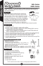
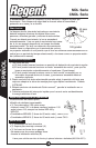
Step 10:Push the wires into the junction box, remove hook and discard. Rotate
the bent bracket to a horizontal position.
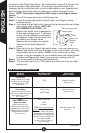
Step 11:Secure the fixture (upright) to the mounting bracket with the two ball
nuts provided (O).
Step 12:Apply silicone caulk around the edges of the
coverplate (O).
How to operate your fixture
Step 1: TURN MAIN POWER ON and then turn indoor wall
switch on.
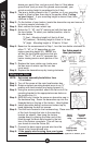
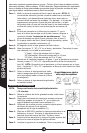
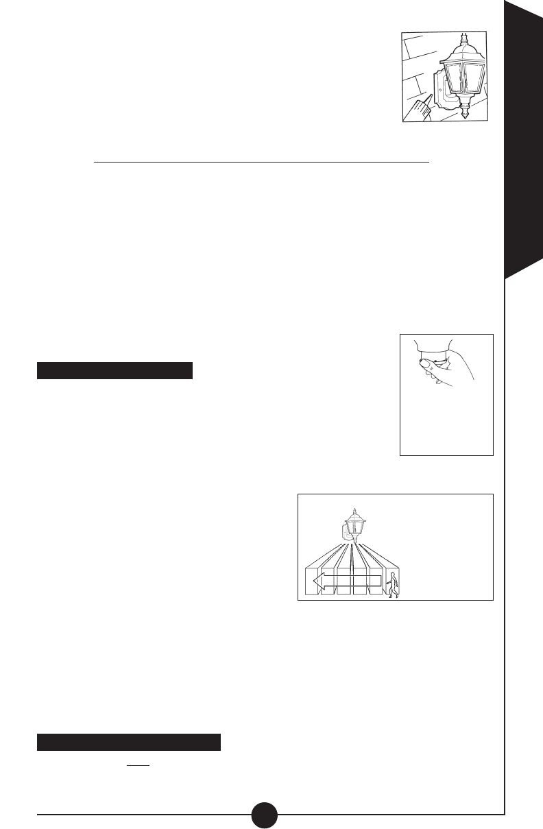
Step 2: Rotate lens in direction of preferred detection area.
Remember: The “L”, “M”, or “H” represents the center
viewing area on each portion of the lens.
For exam-
ple:
If your mounting height is 8 feet and you chose mounting height “L”
on the lens, then the “L” on the front of the lens represents the middle of
the viewing area. When rotating the
lens left or right, use this as the cen-
ter marker. The same is true for the
“M” or “H” position.
Step 3: Make sure the switch on the lantern
base plate is in the TEST position.
Step 4: Wait 90 seconds, then move into the
detection area and the lights will
turn ON. Light will turn off 4 seconds after motion stops.
Step 5: Readjust the detection area as necessary by rotating the lens
Step 6: To adjust detection r
ange (measured in feet), set the sensitivity switch
located on the opposite side of the lantern base plate to “L” (Low), “M”
(Medium) or
“H”
(High).
Step 7: Move slide switch to 4 MIN or 12 MIN (Auto mode) or to one of the three
NIGHT TIME ON mode settings. At dusk, your lantern will operate in
the Auto or Night Time On setting.
Installing your light switch cover
This cover will only fit standard residential light switch toggles up to 1/4” wide.
The light switch cover prevents children and adults from accidentally turning off
Walk across the
detection zone to
determine the
proper adjustments
Gently rotate
lens by grasping
the base (area
directly under
the lens)
O