


7
PYROMASTER® UVHB20 Vent-Free Heaters
20001540
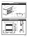
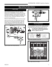
4. Remove the (2) screws holding the bracket to the
fan. Discard this bracket.
5. Remove the two (2) wires attached to the fan and
assemble the fan to the bracket as shown in Figure
6.
6. Attach the fan assembly to the back of the heater
with the three (3) nuts.
7. Attach the electrical flag connectors to the fan
motor using the wire extension (Fig. 5)
8. Feed the wire down the 1-inch diameter hole in the
left side of the radiant shield. Push plastic bushing
in hole.
9. Hook the wire extension to the wire leads from the
fan control box. NOTE: These leads were hooked
to the motor earlier.
10. Mount the thermo-disc to the shield under the
burner pan and secure with two (2) nuts.
11.Mount the fan on-off control to the base with the
studs provided and secure with two (2) nuts.
12. Feed the plug through the 4" x 5" hole on the left
side of the heater and plug into a wall receptacle.
13. Repeat steps 1 through 3 to reassemble the heater.
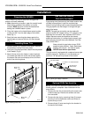
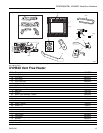
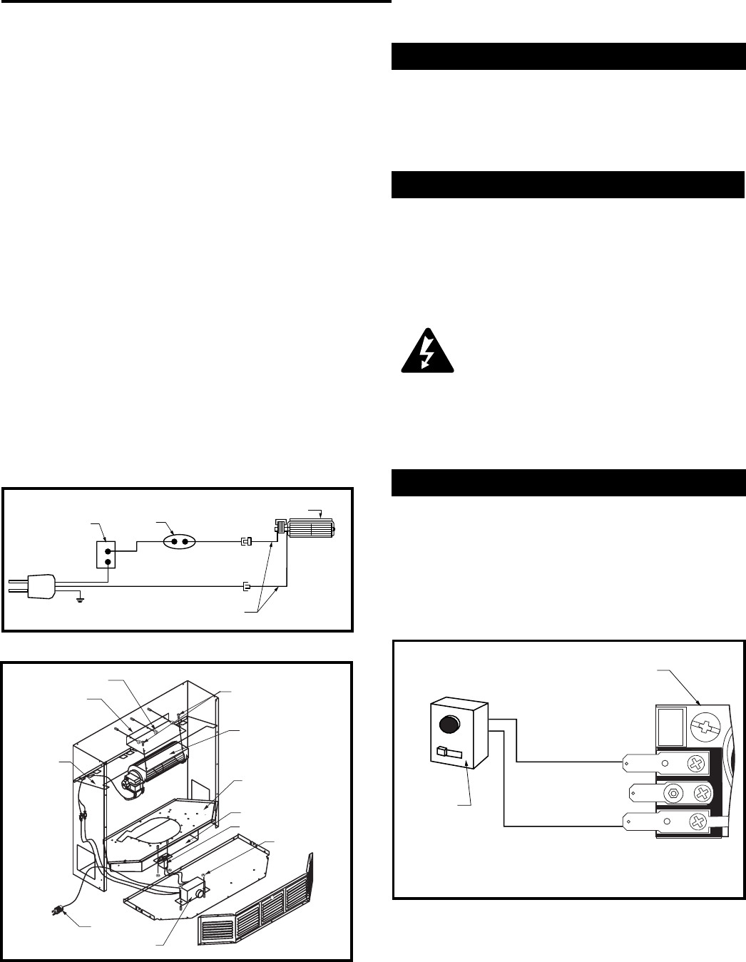
Fig. 5 Wiring diagram.
FP394A
Wire Extension
Speed
Control
Temperature
Sensor
Fan
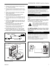
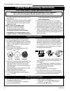
Fig. 6 Parts identification.
FP732
Hex Nut
Screws
Fan
Burner Pan
Shield
Thermo Disk
Hex Nut
Rheostat
To Receptacle
Fan Bracket
Radiant Shield
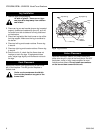
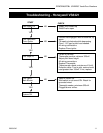
Fig. 7 Remote control receiver wiring.
TPTH
TH
TP
Valve
Remote
Control
Receiver
FP382b
Fan Operation
The FK24 fan has a heat sensor that will not allow the
fan to come on until heater reaches a preset tempera-
ture, approximately 100-120° F. Once the heater
reaches temperature use the speed control knob to turn
fan on and off to adjust fan speed.
Final Assembly
Final assembly is accomplished by lifting the mantel
cabinet overtop of the heater behind the brass trim
pieces.
NOTE: The mantel is designed to fit flush to the wall as
a freestanding unit. If desired, it may be secured to the
wall with nails or screws (not provided).
When installed, the heater must be electri-
cally connected and grounded in accor-
dance with local codes or, in the absence
of local codes:
U.S. INSTALLATIONS: FOLLOW LOCAL CODES
AND THE NATIONAL ELECTRICAL CODE, ANSI/
NFPA NO. 70.
Remote Control (RM2)
The UVHB20 is shipped with a remote control that
allows the unit to be turned on or off from anywhere in
the room. The remote control receiver is wired at the
factory as shown in Figure 7.
Move the switch on the receiver (mounted behind the
door) to the desired position for operation.