


6
PYROMASTER® UVHB20 Vent-Free Heaters
20001540
Run Gas Line from Its
Source to the Heater
If gas piping from the source to the heater location has
not been accomplished, install the required pipe.
Consult local plumbing code to assure proper pipe size.
The gas pipeline can be brought in through the right
side of the heater.
NOTE: The gas line connection can be made with
properly tinned 3/8" copper tubing, 1/2" rigid pipe or an
approved flex connector, then reduced to 3/8" to the
heater. Because some municipalities have some
additional local codes, it is always best to consult your
local authority. Consult the current National Fuel Gas
Code, ANSI Z223.1
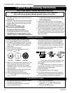
Always check for gas leaks using a 50/50
soap and water solution. Apply water/soap
solution with a brush -
do not over apply.
NEVER!
test with an open flame.
The gas control is equipped with a captured screw type
pressure test point, therefore it is not necessary to
provide a 1/8" test point up stream of the control.
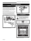
Preparing the UVHB20
The UVHB20 may only be used with the approved
mantel and hearth assembly.
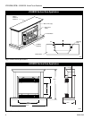
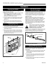
1. After determining a location, open the mantel hearth
base carton and place into position on a solid
surface. NOTE: Be sure to level the base before
setting the UVHB20 heater in place.
2. Place the heater on the hearth base centering side
to side and 3/4" from the back edge of the hearth
base (Fig. 1)
3. Bend the lower mounting tabs down against the
hearth base and secure with two (2) wood screws
(Fig. 1)
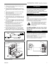
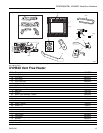
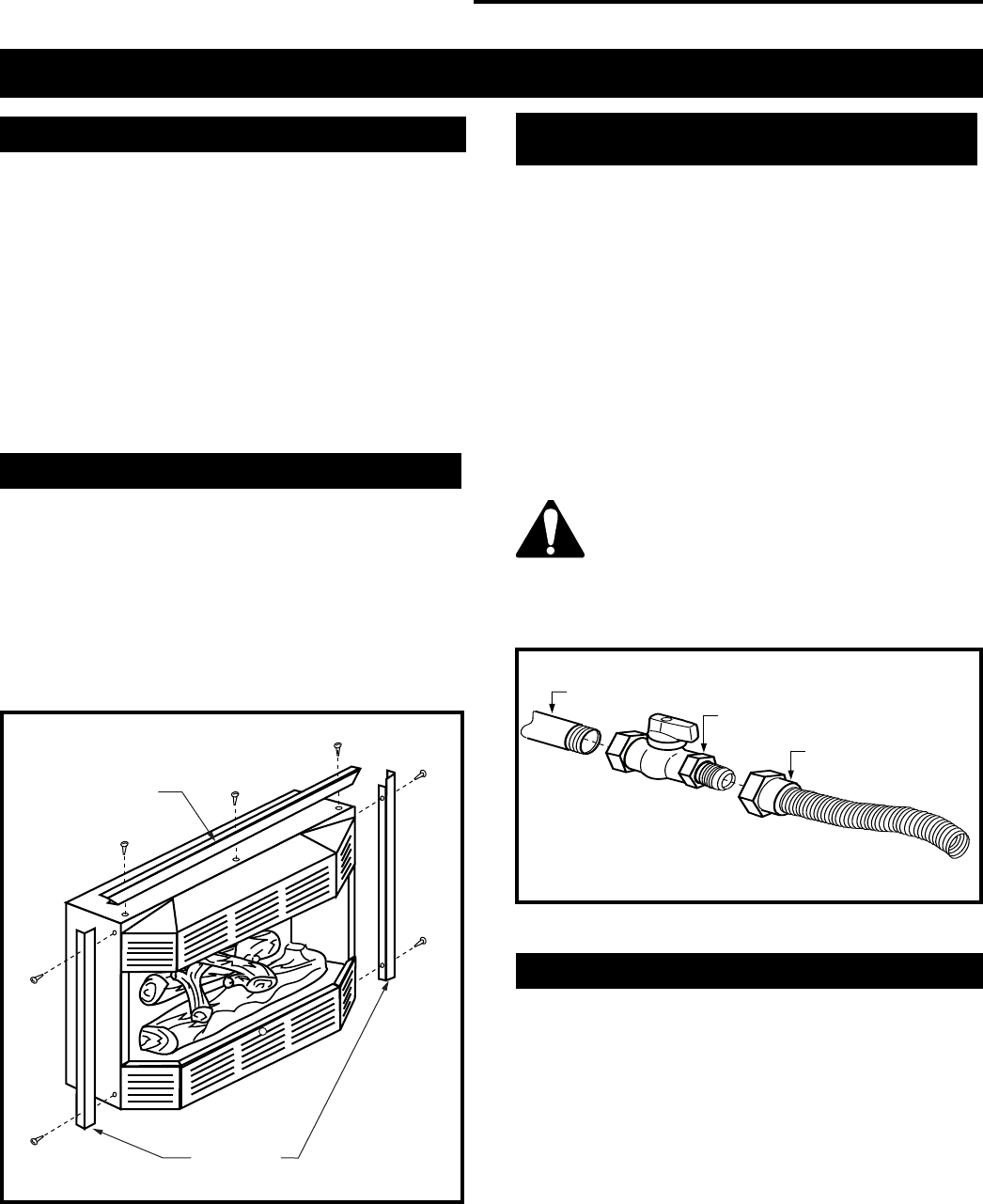
Installing Brass Trim
1. Remove brass trim (3 pieces) from carton. Remove
the protective coating from each piece.
2. Using the (2) screws provided, attach the side pieces
to the heater. (Fig.3)
3. Mount the top trim to the heater. Loosen top three
(3) screws and slide trim under the screws, tighten
the screws. Be sure to overlap top trim to the front
side of the side trim pieces.
Fig. 3 Installing brass trim.
FP731a
Brass Trim
(Top)
Brass Trim
(Sides)
Fig. 4 Typical gas supply installation.
FP297A
1/2" Gas Supply
1/2" NPT x 1/2" Flare Shut-Off
Valve
3/8" Flex Line
(From Valve)
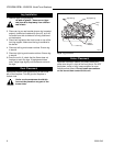
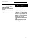
Optional FK24 Fan Hook-Up
NOTE: The FK24 fan should be installed before the
mantel cabinet is complete. Later installation will be
more difficult.
1. Remove the two (2) screws holding the screen rods
inside the bay top. Remove the screen and rods
then set aside.
2. Remove the bay top by removing three (3) screws
securing it to the combustion dome and three (3)
screws on top of unit.
3. Remove three (3) nuts securing the fan bracket to
the back of the heater.
Installation