


6
W415-0514 / 05.30.05
Use only Wolf Steel, Simpson Dura-Vent, Selkirk Direct
Temp or American Metal Amerivent venting components.
For Simpson Dura-Vent, Selkirk Direct Temp and American
Metal Amerivent, follow the installation procedure provided
with the venting components.
For vent systems that provide seals on the inner exhaust
flue, only the outer air intake joints must be sealed using a
red high temperature silicone (RTV). This same sealant
maybe used on both the inner exhaust and outer intake
vent pipe joints of all other approved vent systems except
for the exhaust vent pipe connection to the fireplace flue
collar which must be sealed using the black high tempera-
ture sealant Mill Pac.
Wolf Steel, Simpson Dura-Vent, Selkirk Direct Temp and
American Metal Amerivent venting systems must not be
combined.
A starter adaptor must be used and may be purchased
from the corresponding supplier:
Supplier GAS STOVE
Duravent GDS924N
Amerivent 4DSCB-N1
Direct Temp 4DT-AAN
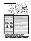
When using Continental venting components, use only the
following vent kits: WALL TERMINAL KIT GD175 (7-1/2' of
venting included), or 1/12 TO 7/12 PITCH ROOF TERMINAL
KIT GD110, 8/12 TO 12/12 ROOF TERMINAL KIT GD111,
FLAT ROOF TERMINAL KIT GD112 or STOVE PERISCOPE
KIT GD180 (for wall penetration below grade) in conjunc-
tion with the appropriate venting components.
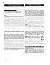
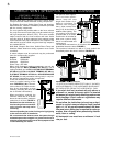
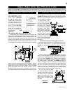
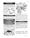
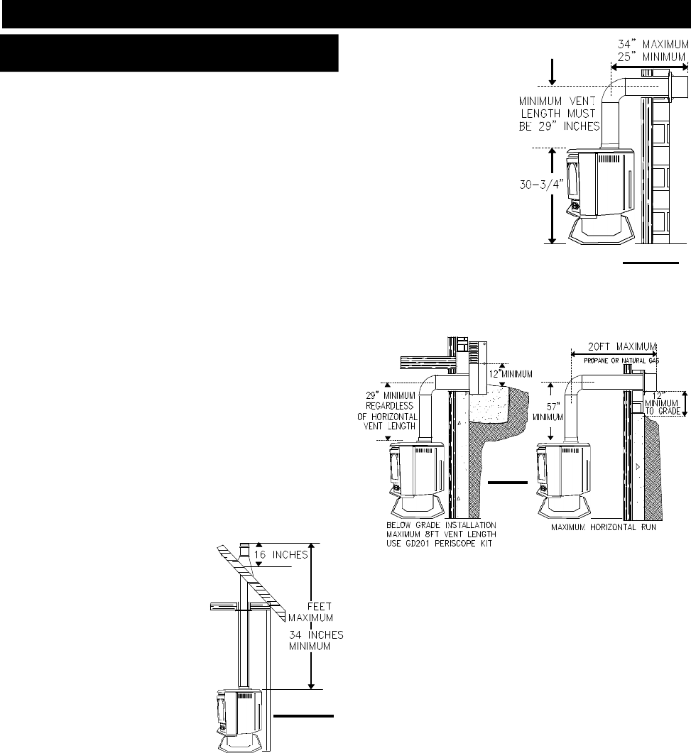
These vent kits allow for either hori-
zontal or vertical venting of the
stove. FIGURES 4, 5, & 6. The maxi-
mum number of 4" flexible connec-
tions is two horizontally or three
vertically (excluding the stove and
the air terminal connections).
When terminating vertically, the
minimum vertical rise is 34 inches
above the stove and the maximum
vertical rise is 40 feet. FIGURE 4.
Deviation from the minimum ver-
tical vent length can create diffi-
culty in burner start-up and/or
carboning.
Use an adjustable pipe as the final length of rigid piping
to the stove for ease of installation.
We recommend that exhaust vents that pass through
unheated spaces be wrapped in a protective sleeve to
minimize condensation and reverse flow symptoms. See
Trouble Shooting for details.
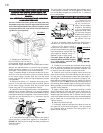
For optimum flame appear-
ance and stove perfor-
mance, keep the vent
length and number of el-
bows to a minimum. On
extreme vent configura-
tions, allow several min-
utes (5-15) for the flame to
stabilize after lighting. The
air terminal must remain
unobstructed at all times.
Examine the air terminal at
least once a year to verify
that it is unobstructed and
undamaged.
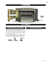
The maximum horizontal run is 34 inches with a 90
o
elbow
located 29" above the stove. FIGURE 5.
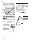
The maximum horizontal run with a 57 inch vertical rise
immediately above the stove is 20 feet FIGURES 6.
IF VERTICAL RISES GREATER THAN 57 INCHES
ARE NECESSARY, THE INCREASED RISE MUST
BE DEDUCTED FROM THE HORIZONTAL RUN.
A terminal shall not terminate directly above a
sidewalk or paved driveway which is located
betweeen two single family dwellings and serves
both dwellings. Local codes or regulations may
require different clearances.
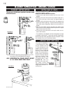
Do not allow the inside liner to bunch up on hori-
zontal or vertical runs and elbows. Keep it pulled
tight. a 1-1/4" air gap all around between the inner
liner and outer stove pipe is required for safe op-
eration. Use a firestop when penetrating interior
walls, floor or ceiling.
All horizontal runs must have a minimum ¼ inch
rise per foot.
FIGS 6
FIGURE 5
HORIZONTAL RUN NOT TO EXCEED VERTICAL RISE
FIGURE 4
DIRECT VENT SPECIFICS - MODEL CDVS500
VENTING LENGTHS &
AIR TERMINAL LOCATIONS
40