


13
W415-0514 / 05.30.05
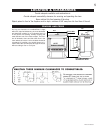
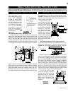
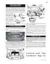
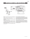
Remove nails from the shingles above and to the sides of
the chimney. Place the flashing over the vent pipe and slide
it underneath the sides and upper edge of the shingles.
Ensure that the vent pipe is properly centered within the
flashing, giving a 3/4" margin all around. Fasten to the roof
on the top and sides. DO NOT NAIL through the lower
portion of the flashing.
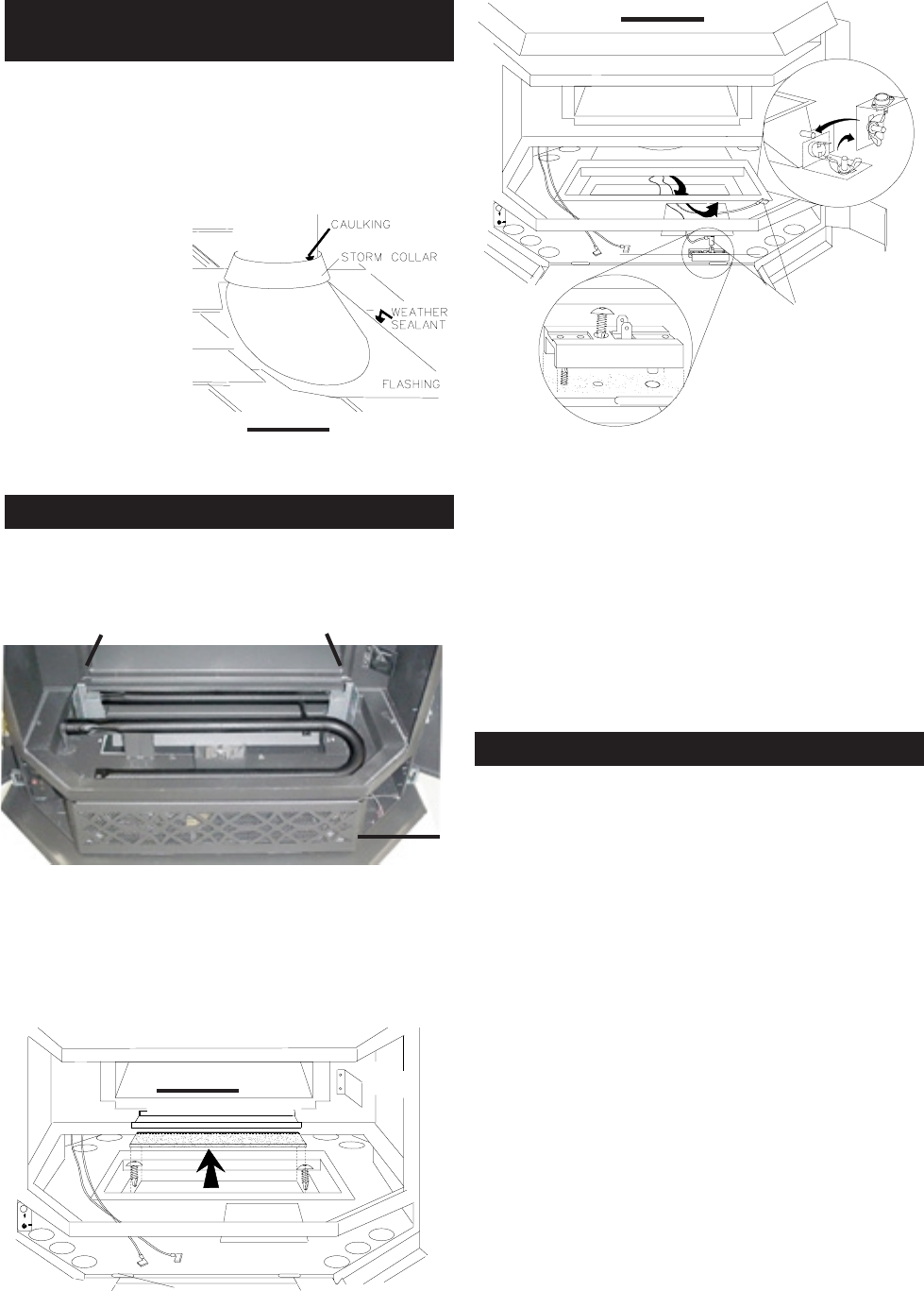
Make weather-tight by
sealing with caulking.
Where possible, cover
the sides and top
edges of the flashing
with roofing material.
Apply waterproof
caulking around the
vent, 1" above the top
of the flashing and
push the
storm collar down into the caulking. Attach a rain cap to the
top of the last vent section.
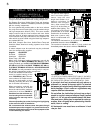
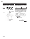
Read the section on opening the door in "Finish-
ing" prior to proceeding to prevent damaging the
unit.
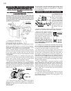
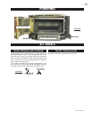
1. Remove both burners and the log support bracket.
2. Remove the combustion air cover plate and its gasket.
THE TWO SCREWS MUST BE RE-SECURED. FIGURE 30.
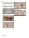
3. Undo the bracket holding the thermodisc, turn 90° as
shown and reattach to the weld stud located on the right
air manifold side. FIGURE 31. (Do not tighten the wing nut
until burner is installed; then ensure that the switch firmly
touches the underside of the burner tray and tighten. This
enables the blower to function properly.)
4. Secure the terminal block into place as shown with the
screw supplied. FIGURE 32.
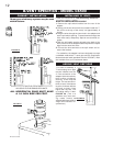
5. Gently pull the two white spill switch wires to take up any
slack. Feed these wires down through the combustion air
opening and back up through the 4x6 inch cut-out in the
base. Connect the shorter of the 2 wires to the terminal
block.
6. Attach the black on/off switch wire with the 3/16" tab to
the other side of the terminal block. Connect the remaining
wires (1 black - 1 white) with ¼" connectors to TP/TH and
TH on the gas valve.
7. Replace and re-secure the log support bracket and the
two burners ensuring that each venturi fits over the burner
orifice.
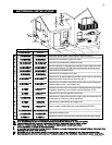
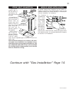
ANY STOVE NEEDS AIR FOR SAFE OPERATION AND
MUST BE INSTALLED IN SUCH A WAY THAT ADEQUATE
COMBUSTION AIR IS AVAILABLE. THIS UNIT IS DE-
SIGNED TO FUNCTION USING EITHER OUTSIDE OR IN-
SIDE (ROOM) AIR.
If using outside air, connections can be made through a
hole in the floor to line up with the hole in the pedestal
base. Use a fresh air kit available through your Continental
Fireplace dealer or Wolf Steel Ltd. Secure the 4" diameter
aluminium liner to the hole in the base of the pedestal.
Avoid cutting away floor joist, electrical wiring or plumbing.
Seal around the outside pipe with insulation to prevent
drafts.
Continue with "Gas
Installation" Page 14
TURBO
VIEWING
COMBUSTION AIR COVER PLATE
MIRROR
FIGURE 31
FIGURE 32
SPILL SWITCH
WIRES
FIGURE 29
FIGURE 30
LOG SUPPORT BRACKET
REAR BURNER
FRONT BURNER
INSTALLING FLASHING
AND STORM COLLAR
'B' VENT ADAPTATIONS
COMBUSTION AIR