


10
W415-0514 / 05.30.05
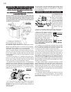
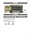
FIGURE 17
FOR SAFE AND PROPER OPERAFOR SAFE AND PROPER OPERA
FOR SAFE AND PROPER OPERAFOR SAFE AND PROPER OPERA
FOR SAFE AND PROPER OPERA
TION OF THETION OF THE
TION OF THETION OF THE
TION OF THE
STST
STST
ST
OO
OO
O
VE, FOLLVE, FOLL
VE, FOLLVE, FOLL
VE, FOLL
OO
OO
O
W THE VENTING INSTRW THE VENTING INSTR
W THE VENTING INSTRW THE VENTING INSTR
W THE VENTING INSTR
UCTIONSUCTIONS
UCTIONSUCTIONS
UCTIONS
EXAEXA
EXAEXA
EXA
CTLCTL
CTLCTL
CTL
YY
YY
Y
..
..
.
ALL HORIZONTALL HORIZONT
ALL HORIZONTALL HORIZONT
ALL HORIZONT
AL RAL R
AL RAL R
AL R
UNS MUST HAUNS MUST HA
UNS MUST HAUNS MUST HA
UNS MUST HA
VE A MINIMUMVE A MINIMUM
VE A MINIMUMVE A MINIMUM
VE A MINIMUM
¼ INCH¼ INCH
¼ INCH¼ INCH
¼ INCH
RISE PER FOO RISE PER FOO
RISE PER FOO RISE PER FOO
RISE PER FOO
TT
TT
T
..
..
.
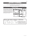
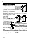
1. Stretch the 4" diameter alu-
minum flexible liner to the re-
quired length taking into account
the additional length needed for the finished wall surface.
Spacers are attached to the 4" inner flex liner at predeter-
mined intervals to maintain a 1-1/4" air gap to the 7" outer
stove pipe. These spacers must not be removed.
Slip a 4" diameter length of aluminum flexible liner a mini-
mum of 2" over the inner sleeve of the air terminal. Secure
to the sleeve using 3 screws. Seal the joint and screw
heads using red RTV or Mill Pac high temperature sealant
(not supplied).
2. Slip the first section of 7" diameter stove pipe a mini-
mum of 2" over the outer sleeve of the air terminal. Secure
to the sleeve using 3 screws. Seal the joint and screw
heads using red RTY high temperature sealant.
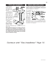
3. Insert the liners through the firestop / vent pipe shield.
Holding the air terminal (lettering in an upright, readable
position), secure to the exterior wall. Make weather tight by
sealing with caulking (not supplied). The air terminal mount-
ing plate may be recessed (up to
3
/
4
" maximum) into the
exterior wall or siding.
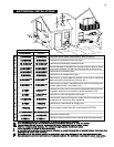
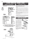
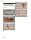
4. If more than one length of liner needs to be used to
reach the stove, couple them together as illustrated in
FIGURE 18. Seal the joints using the same procedure as
described above.
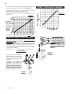
The vent system must be supported approximately every
10 feet along a horizontal run. Use supports or equivalent
non-combustible strapping to maintain the 1" clearance
from combustibles.
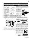
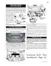
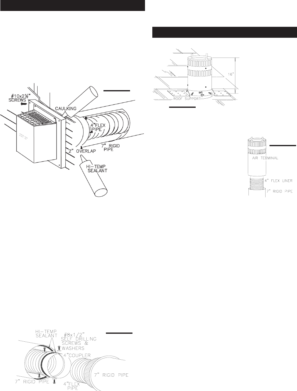
1. Fasten the roof
support to the roof us-
ing the screws pro-
vided. The roof support
is optional. The venting
is to be adequately
supported using either
an alternate method
suitable to the authority
having jurisdiction or
the optional roof sup-
port.
2. Slip a 4" diameter length of aluminum flexible liner a
minimum of 2" over the inner sleeve of the air terminal.
Secure to the sleeve using 3
screws and flat washers. Seal the
joint and screw heads using red RTV
high temperature sealant Mill Pac
(not supplied). Repeat using a 7"
diameter length of rigid piping.
If the attic space is tight, we rec-
ommend adding sufficient lengths
of 7" rigid piping, secured and
sealed as necessary.
3. Thread the air terminal pipe assembly down through
the roof support and attach, ensuring that a minimum 16"
of air terminal will penetrate the roof when fastened. The
air terminal must be located vertically and plumb.
4. Remove nails from the shingles, above and to the
sides of the chimney. Place the flashing over the air termi-
nal and slide it underneath the sides and upper edge of
the shingles. Ensure that the air terminal is properly cen-
tered within the flashing, giving a 3/4" margin all around.
Fasten to the roof. Do NOT nail through the lower portion of
the flashing. Make weather-tight by sealing with caulking.
Where possible, cover the sides and top edges of the flash-
ing with roofing material.
5. Apply a heavy bead of waterproof caulking 2 inches
above the flashing. Slide the storm collar around the air
terminal and down to the caulking. Tighten to ensure that a
weather-tight seal between the air terminal and the collar
is achieved. Attach the other storm collar centered between
the air intake and air exhaust slots onto the air terminal.
Tighten securely.
6. Attach the vertical rain cap.
7. In the attic, slide the vent pipe collar down to cover up
the open end of the shield and tighten. This will prevent
any materials, such as insulation, from filling up the 1" air
space around the pipe.
FIGURE 18
FIGURE 19
FIGURE 20
HORIZONTAL VENTING INSTALLATION
VERTICAL VENTING INSTALLATION
All inner exhaust and outer intake vent pipe joists may
be sealed using either Red RTV high temp silicone seal-
ant or Black high temp Mill Pac with the exception of the
fireplace exhaust flue collar which must be sealed us-
ing Mill Pac (not supplied).