


Page -10- Clarke
®
Operator's Manual -FOCUS S17/L17 and S20/L20
EN
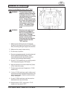
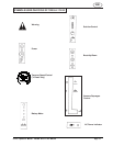
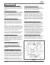
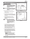
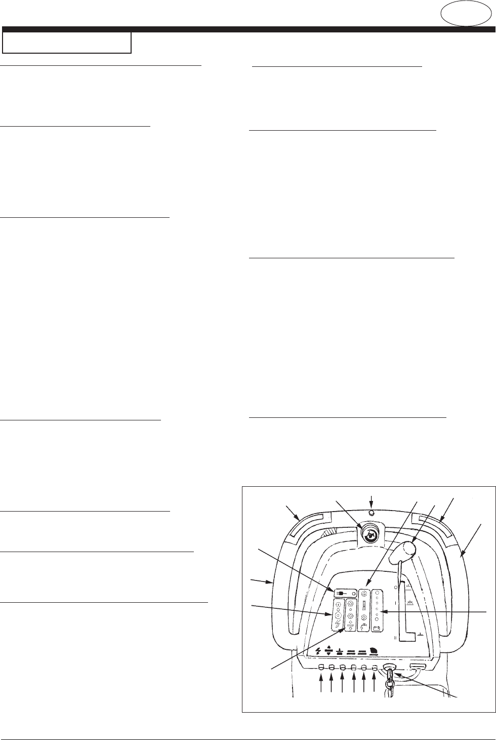
Machine Control Panel
Figure 3
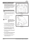
Reverse Switch (See Figure 3, Item "H")
On Traverse "L" Models Only - The reverse switch,
when used in conjunction with one of the forward/reverse
switches, causes the machine to reverse directions. The
reverse speed is 70% of the forward speed.
Brush Motor Buttons (See Figure 3, Item "I")
To lower brush head and activate brush motor(s) and
solution flow, press and hold the down button until the
green light is illuminated. Continue to press and hold
down button for additional brush pressure, or until brush
head stops. The brush motor(s) and solution will then
operate when either one or both of the forward/reverse
button(s) are pressed. To deactivate the brush motor(s)
and solution flow, raise the brush head by pressing and
holding the up button until the green indicator light turns
off.
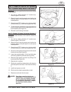
Solution Control Buttons (See Figure 3, Item "J")
The solution control buttons regulates the flow of chemi-
cal solution to the floor. When powering up the machine,
the solution setting will automatically adjust to the mid
setting (see your authorized Clarke serviceman if a
different setting is preferred). To increase the flow, press
and hold or press the upper button (+) multiple times.
The green bar will move up the scale as the flow in-
creases. To decrease the flow, press and hold or press
the lower button (-) multiple times. The green bar will
move down the scale as the flow decreases. When the
bar reaches the lowest setting the solution flow is turned
"OFF". NOTE: The solution will only flow when the
brush head is down and in the operating position.
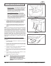
Vacuum Motor Switch (See Figure 3, Item "K")
To activate the vacuum motor, lower the squeegee
handle. The handle has three positions. Lowest position
is the operating water pickup position. The center
position is used during transport to clear vacuum hose.
The upper position is the vacuum motor "OFF" position.
Electrical Power Indicator
(See Figure 3, Item "A")
A yellow light will be illuminated when the charger is
plugged into an AC electrical outlet. The electrical cord
must be unplugged and stowed before operating the
machine.
Key Switch (See Figure 3, Item "B")
The key switch is standard on the "L" models. It is used
primarily for preventing unauthorized use by removing
the key. To turn the control panel "ON", the key switch
must be turned clockwise and then the green "ON"
button must be pressed (see item "C"). To turn the
control panel "OFF", turn the key switch counterclock-
wise.
ON/OFF Buttons (See Figure 3, Item "C")
Pressing the green button turns "ON" the power to the
control panel (if the machine is equipped with a key
switch, first turn the key clockwise). Pressing the red
button turns "OFF" power to the control panel (if the
machine is equipped with a key switch, the power can
also be turned "OFF" by turning the key counterclock-
wise.)
NOTE: The "L model" machine is equipped with self
diagnostics and will sometimes fail to operate if a fault
is detected. Once the fault is corrected the machine can
be reset by turning the power "OFF" and turning it back
"ON". If this fails to correct the problem, contact your
authorized service personnel immediately.
NOTE: This machine is equipped with a battery power
saving device. If the machine is unattended for more
than 16 minutes, it will automatically shut itself off.
Battery Meter (See Figure 3, Item "D")
The battery meter indicates the relative charge of the
battery pack. The meter has two green, one yellow and
one red light. When the light switches to "red" the
brush(es) and solution flow will stop. All other functions
will continue to operate. The batteries must then be
immediately recharged to prevent shortening the life of
the battery pack.
Control Handles (See Figure 3, Item "E")
The control handles are located at the rear of the
machine. They are used to guide the machine.
Traverse Speed Knob (See Figure 3, Item "F")
To increase speed, turn knob clockwise. The machine
will not traverse when the knob is turned fully counter-
clockwise.
Forward/Reverse Switch (See Figure 3, Item "G")
On Traverse "L" Models Only - The forward/reverse
switch starts the traverse motor forward and when the
brush head is in the down or scrub position it also
activates the brush motor(s) and solution flow. There is
a two second delay for the brush motor(s) to stop after
releasing the switch. Either the right or the left switch
can be used. Use either switch in conjunction with the
white reverse switch to reverse the traverse motor.
"S" Model - On the non-traverse models these
switches activate the brush motor(s) and solution flow
when the brush head is in the down or scrub position.
A
E
C
I
G
F
H
J
K
G
D
E
B
QP0
N
ML