


3-2
Cisco ASA 5505 Adaptive Security Appliance Hardware Installation Guide
OL-18362-01
Chapter 3 Installing the Cisco ASA 5505
Connecting the Interface Cables
a. Ethernet ports
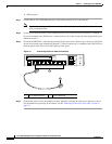
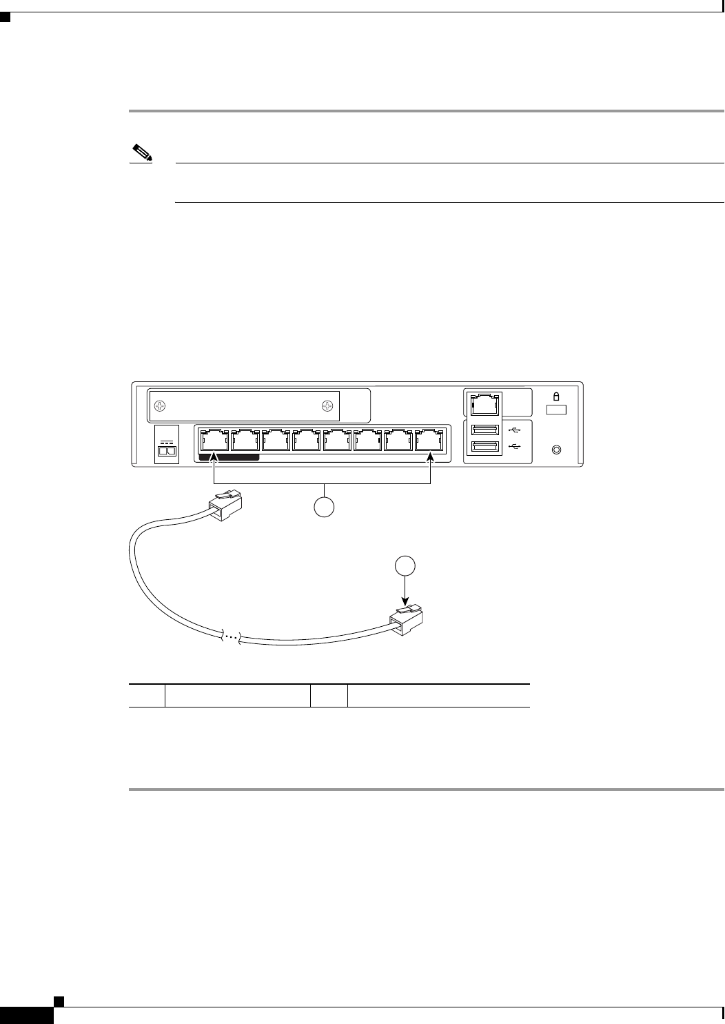
Step 1 Connect Port 0, the outside Ethernet port, to the public network, that is, the Internet:
Note By default, switch port 0/0 is the outside port. If needed you can change the inside and outside
ports assignments later.
Step 2 Connect your network devices with an Ethernet cable to one of the inside ports (numbered 1 through 7).
If you are connecting any PoE devices, connect them to one of the switch ports that support PoE (ports
numbered 6 and 7).
Step 3 Check the LINK LED to verify that the network devices have basic connectivity to the Cisco ASA 5505
on one of the inside ports (numbered 0 through 7). When connectivity is established, the LINK LED on
the front panel of the Cisco ASA 5505 lights up solid green.
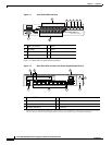
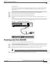
Figure 3-1 Connecting Cables to Network Interfaces
Step 4
Connect the power cord to the adaptive security appliance and plug the other end to the power source.
For information on powering on the chassis, see the “Powering on the Cisco ASA 5505” section on
page 3-3
1 RJ-45 Ethernet ports 2 RJ-45 connector
153646
Security
Services
Card Slot
1
2
Console
RESET
power
48
VDC
7 POWER over ETHERNET 6
543210
2
1