


2-2
Installation and Upgrade Guide for Cisco Unified Videoconferencing 3522 BRI Gateway and 3527 PRI Gateway Release 5.5
OL-14910-01
Chapter 2 Setting Up Your Cisco Unified Videoconferencing 3500 Gateway
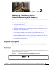
Physical Description
Cisco Unified Videoconferencing 3527 PRI Gateway Rear Panel
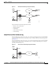
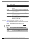
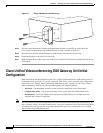
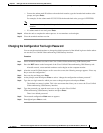
Figure 2-2 shows the rear panel components of the Cisco Unified Videoconferencing 3527 PRI Gateway
unit. Table 2-2 describes these components.
Figure 2-2 Cisco Unified Videoconferencing 3527 PRI Gateway: Rear Panel
Table 2-1 Front Panel Components
Component Description
10/100 BaseT connector An RJ-45 connector that provides the primary Ethernet connection for the IP
network port.
SERIAL connector A DB-9 connector that allows you to connect a PC terminal for local
configuration.
RST button Allows you to reset the Cisco Unified Videoconferencing 3500 Gateway unit
manually.
GK Reg LED Lights green when the Cisco Unified Videoconferencing 3500 Gateway unit
is registered with a gatekeeper.
CD LED Lights green when a PRI or BRI line is enabled and a carrier signal is
detected
ACT LED Lights green to indicate that there are active calls in the Cisco Unified
Videoconferencing 3500 Gateway unit.
ALARM LED Lights green to indicate that an error has occurred and the Cisco Unified
Videoconferencing 3500 Gateway unit requires resetting.
10/100 BaseT LEDs The top part of the 10/100 BaseT connector contains two LED indicators.
The left-hand LED lights green when the local IP network link is active. The
right-hand LED lights green if the connection speed is 100 Mbps, and is off
when the connection speed is 10 Mbps.
Table 2-2 Cisco Unified Videoconferencing 3527 PRI Gateway Rear Panel Components
Component Description
ACT LED Lights green to indicate that there are active calls in the gateway.
D-Ch LED Lights green to indicate that the PRI line is enabled and a carrier signal is
detected.
PORT-1PORT-2
ACT
1
57266
D-Ch
ALARM
ACT
D-Ch
ALARM