


NOTE: For additional trouble shooting information, see MANUAL
A/C-HEATER SYSTEMS - TROUBLE SHOOTING article.
BLOWER MOTOR
1) If blower does not operate, check HVAC fuse (20-amp) in
instrument panel fuse block. If fuse is blown, check for short to
ground in Brown wire between HVAC fuse (20-amp) and mode selector
switch 3-pin connector terminal "C". If fuse is okay, check I/P-1 fuse
(40-amp) in underhood electrical center. If fuse is blown, check for
short to ground in Red wire between I/P-1 fuse (40-amp) and blower
motor relay harness connector terminal A2.
2) Ensure ground connectors located near left or right "A"
pillar, bolted to instrument panel mounting stud behind kick panel are
clean and tight. Check for a broken or partially broken wire inside of
insulation which could cause system malfunction but prove good in a
continuity/voltage check with system disconnected. Check for proper
installation of aftermarket electronic equipment.
SYSTEM TESTS
WARNING: To avoid injury from accidental air bag deployment, read and
carefully follow all SERVICE PRECAUTIONS and DISABLING &
ACTIVATING AIR BAG SYSTEM procedures in AIR BAG SYSTEM SAFETY
article in GENERAL SERVICING.
A/C SYSTEM PERFORMANCE
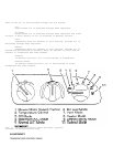
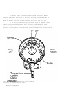
1) Rotate temperature control knob from full cold to full hot
and back to full cold. Listen for temperature valve to seat in both
full hot and full cold position. If temperature valve seats in both
positions, go to next step. If temperature valve does not seat in both
positions, go to step 4).
2) Park vehicle out of direct sunlight. Close doors and
windows. Open driver’s window 5-6" (127-152 mm). Open engine hood.
Place vehicle in Park (A/T) or Neutral (M/T), and set parking brake.
Set temperature control to maximum cold, maximum A/C, and blower to
high speed. Start engine and go to next step.
3) Observe A/C compressor. If compressor engages, go to next
step. If compressor does not engage, see A/C COMPRESSOR CLUTCH
CONTROLS - ALL MODELS article.
4) Check cooling fan operation. If both cooling fans are
operating, go to next step. If both cooling fans are not operating,
see ELECTRIC COOLING FANS - ALL MODELS article.
5) Connect A/C manifold gauge set. Place thermometer at
instrument panel center vent. Set temperature control to maximum cold,
maximum A/C, and blower to high speed. Run engine at idle for 2
minutes. Note high-side and low-side pressures on A/C manifold gauge
set. Determine relative humidity and ambient air temperature.
Ensure system is operating within specified range. See
A/C SYSTEM PERFORMANCE PRESSURE SPECIFICATIONS (2000 MODELS) and
A/C SYSTEM PERFORMANCE TEMPERATURE SPECIFICATIONS (2000 MODELS)
tables. Also see
A/C SYSTEM PERFORMANCE PRESSURE SPECIFICATIONS (2001 MODELS) and
A/C SYSTEM PERFORMANCE TEMPERATURE SPECIFICATIONS (2001 MODELS).
6) If system is operating within specified range, system is
okay. If system is not operating within specified range, check
Variable Displacement Orifice Tube (VDOT) system. See MANUAL A/C-
HEATER SYSTEMS - TROUBLE SHOOTING article.
A/C SYSTEM PERFORMANCE PRESSURE SPECIFICATIONS (2000 MODELS)