


15
Stardance Direct Vent/Natural Vent Gas Heater
20007065
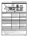
Install the Vent Adapter Pipe
(Simpson Dura-Vent Components)
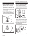
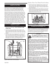
1. Install the Restrictor Plate. Consult the ‘Vent Run
Specifications’ on Page 8 to determine whether the
restrictor plate is needed. If so, put the restrictor
plate in place within the inner flue collar. (Fig. 16)
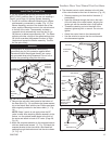
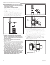
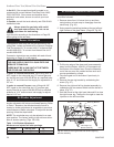
2. Discard the inner starter pipe shipped with the log-
set. Using the starter pipe assembly listed on Page
7, slide the inner section out to allow access.
• Run a bead of sealant around the bottom end of
the starter pipe and attach the assembly to the stove
using three 1/4-20 x 3/8” Phillips screws provided in
the parts bag. (Fig. 20)
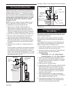
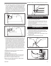
3. Install the Outer Adapter Pipe. Apply a 1/4” bead of
cement around the outside surface, about one inch
from the crimped end. (Fig. 21) Orient the vertical
seam to the rear, and insert the crimped end of the
outer pipe into the flue collar. Fasten with three sheet
metal screws provided.
ST355
dura v
ent
attach inner assy
4/7/00 djt
CEMENT
1/4-20 x
3/8 Phillips
Screws
Inner Adapter
Pipe
ST355a
Fig. 20 Simpson Dura-Vent - install inner adapter pipe.
ST356
dura v
ent
attach outer assy
4/7/00 djt
ST356a
Fig. 21 Simpson Dura-Vent - install outer adapter pipe.
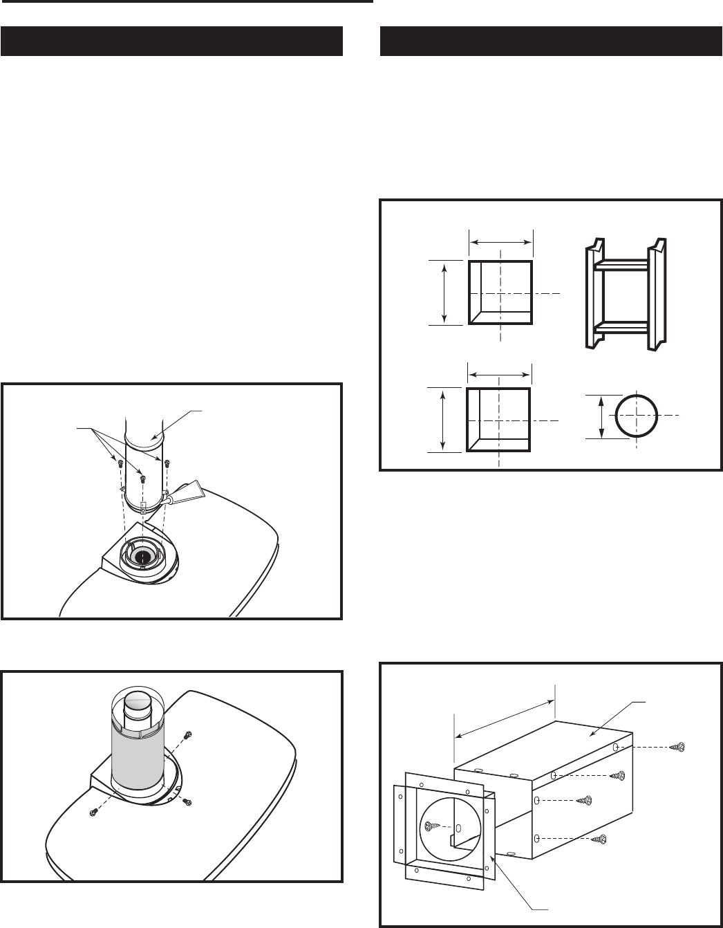
Side Wall Termination Assembly
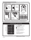
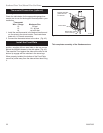
1. Locate the vent opening on the wall. Refer to Fig-
ure 4, Page 6, to determine the opening centerline.
It may be necessary to first position the stove and
measure to find the hole location. Depending on
whether the wall is made of combustible materials,
cut the opening to the size shown in Figure 23. Com-
bustible wall openings must be framed as shown in
Figure 22.
VO584-100
Vent Opening
2/99 djt
CFM System
9³⁄₈”
(240mm)
9³⁄₈”
(240mm)
Combustible Wall
Framing Detail
DuraVent
System
10”
(254 mm)
7¹⁄₂”
(191 mm)
Noncombustible Wall
VO584-100
Fig. 22 Locate vent opening.
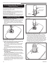
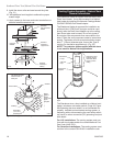
2. Measure the wall thickness and cut the wall sleeve
sections to proper length (MAXIMUM 12”). Assemble
the sleeve with the #8 sheet metal screws supplied.
Attach the firestop plate to the sleeve end with the
holes. (Fig. 23) NOTE: The wall sleeve is required
in combustible walls only.
3. Install the Wall Firestop/Sleeve assembly into the
wall cutout and fasten the firestop to the wall cutout
framing members. (Fig. 23)
ZCS103
Zero Clearance Sleeve
& Firestop
12/6/99 djt
12”
(305 mm)
Max. Length
Sleeve
#8 Sheet
Metal Screws
Firestop
ZCS103
Fig. 23 Assemble the wall sleeve and firestop.