


13
Stardance Direct Vent/Natural Vent Gas Heater
20007065
Install the Optional Fan
If you are installing the optional convection Fan Kit
#2767 (FK26), continue here. If you are not installing a
Fan Kit, go to Page 14, Venting System Assembly.
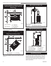
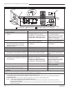
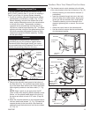
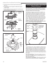
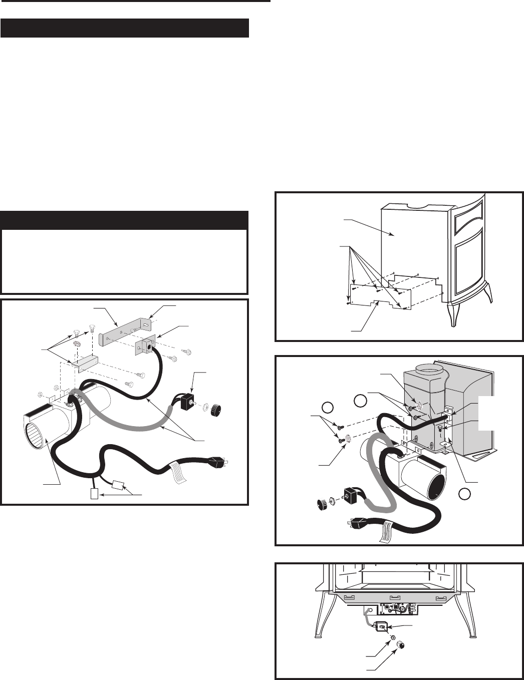
1. The fan kit includes a Blower Assembly and a Rheo-
stat Assembly, connected by a cable. (Fig. 12) The
Blower Assembly mounts to the bottom rear of the
stove, and the Rheostat mounts to the valve bracket
to the left of the valve. The assembly includes a
‘snapstat’ which automatically turns the fan On (or
Off) above (or below) approximately 109˚. The Rheo-
stat also provides a range of fan speed settings from
Off (which overrides the snapstat function) to High.
Unpack and inspect the Blower assembly. Confirm
the fan spins freely.
WARNING
This appliance is equipped with a three-prong
(grounded) plug for your protection against shock
hazard and should be plugged directly into a prop-
erly grounded three-prong receptacle. Do not cut or
remove the grounding prong from this plug.
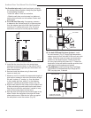
4. The rheostat control switch attaches to the left side
of the valve bracket at the front of the stove. (Fig. 15)
• Remove retaining nut from shaft of rheostat. (if
preinstalled)
• Insert the rheostat through the hole in the back
of the left side of the valve bracket, aligning the
locator pin with the smaller hole in that bracket.
• Thread the retaining nut onto the shaft of the
rheostat, tightening with a wrench. Do not over-
tighten.
• Attach the control knob to the rheostat shaft.
• Use the wire tie to secure the fan and rheostat
wire harnesses together.
ST473
Fan parts
#2767 FK26
9/29/00
Not Used on RF Models
Not Used on
Stardance
Snapstat Bracket
Snapstat/
Extension
Assembly
Rheostat
Assembly
Not Used
on RF
Models
Connect to PC Board on
RF Models Only
Blower
Assembly
ST473
Fig. 12 Fan kit components.
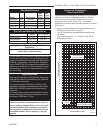
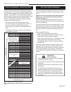
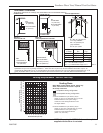
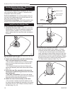
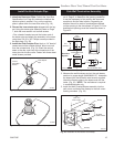
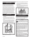
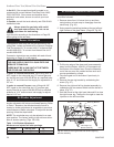
2. Remove the rear skirt insert panel at the bottom of
the Rear Skirt (Fig. 13) and fasten the blower assem-
bly to the firebox back with the two Phillips pan-head
bolts originally installed in the firebox back. (‘1’, Fig.
14)
NOTE: Steps 3 and 4 do not apply when the RF
valve is used. After attaching blower assembly to the
firebox, run the spliced female leads to the front of
the stove and attach to back of RF valve. (Page 28,
Fig. 51)
3. Attach the snapstat assembly to the snapstat bracket
with two sheet-metal screws. (‘2’, Fig. 15) Attach the
snapstat bracket to the stove with a hex-head bolt
passing through the bracket and into the stove base.
(‘3’, Fig. 14)
ST313
fk26
install fan kit
rear skirt insert
1/24/00
Rear Skirt
Sheet Metal
Screws
Rear Skirt
Insert
ST313
Fig. 13 Remove rear skirt insert.
ST314
Fk26ce
attach fan
1/24/00
Star Washer
Sheet Metal Screws
Phillips
Pan Head
Bolts
Star
Washer
NOTE: Shown
without shell for
clarification
Snapstat
Bracket
Snapstat
1/4” - 20
Hex Bolt
3
2
1
ST314
Fig. 14 Attach the fan assembly and the snapstat.
ST347a
JUV
FK28
rheostat install
9/21/00
Rheostat Retaining
Collar
Rheostat Knob
ST347a
Fig. 15 Attach the fan rheostat.