


25
Stardance Direct Vent - Rear Vent Gas Heaters
20012950
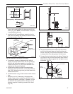
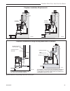
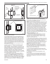
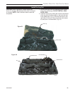
Wall
Thimble
Shield
Seal with RTV
Silicone Sealant
on Exterior side
here (around
perimeter)
Wall Thimble
Shield
Wall
Thimble
Face
Plate
Wall Thimble
Face Plate
ST930
Fig. 43 Wall thimble.
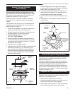
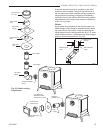
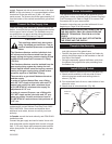
a Vinyl Siding Standoff (VS) must be installed prior to
installing the horizontal termination. Refer to the appli-
ance manufacturer to determine if one is recommend-
ed. Attach the vinyl siding standoff to the exterior side
of the wall (making sure it is level and centered with
respect to the opening) with screws (provided) at each
corner of the standoff. Attach the horizontal termination
to the standoff. (Fig. 45)
If the wall is brick or concrete, and contains no com-
bustible material, a 7” (178 mm) round penetration
hole is adequate. The wall thimble is not required. The
perforated straps of the horizontal termination provide
a method of attachment. These can either be threaded
through the opening or wall thimble (if used) and
screwed to the pipe or removed with a pair of tin snips
if not used. Use proper masonry fasteners to attach the
horizontal termination to the wall.
7. If a wall thimble is used, push the pipe (which is
connected to the appliance) carefully through the wall
thimble until the DIRECT-TEMP pipe becomes fully
engaged with the horizontal termination. If no thimble is
used, place the Trim Plate (TP) on the DIRECT-TEMP
pipe. Carefully push the DIRECT-TEMP pipe through
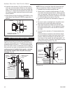
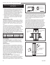
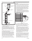
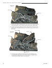
Horizontal Termination
ST931
Fig. 44 Horizontal termination.
ST932
Selkirk standoff
6/07
Vinyl Siding Standoff
ST932
Horizontal Termination
Fig. 45 Vinyl siding standoff and horizontal termination.
the wall until fully engaged with the horizontal termina-
tion. Secure the trim plate to the wall.
NOTE: If a vertical rise is necessary on the exterior side
of the building, a 14” (356 mm) and 36” (914 mm) Snor-
kel Termination (ST) is available. Follow the installation
procedures for horizontal terminations. If the snorkel
termination is to be located below grade, a window well
is recommended with adequate and proper drainage
as per local codes. Leave 2” (51 mm) clearance be-
low snorkel to prevent water from entering the snorkel
termination. Do not enclose the snorkel within a wall or
other type of enclosure and do not back fill. Ensure
that grade level slopes away from the building. (Fig. 42)
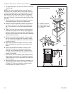
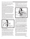
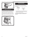
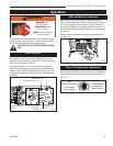
Vertical Installation (Fig. 46)
1. Determine the location of the appliance. Choose
a location which provides adequate clearance from
obstacles such as electrical wiring, conduit, framing
members, plumbing pipe, etc.
2. After positioning the appliance, determine where the
vent pipe will pass through the ceiling. This can be done
by using a plum bob or a small weight attached to a
string. Hold the plum bob from the ceiling moving it until
it lines up with the centerline of the outlet of the appli-
ance. Mark the position on the ceiling.
NOTE: Frame openings to the dimensions specified
in the framing table for the cathedral ceiling support
box (CCS), the ceiling support (SC) and wherever the
firestop spacer (FS) is being used.
3. Cut and frame the appropriate sized square hole
through the ceiling. Repeat the process for other ceiling
penetrations as necessary.
4. Determine and mark the roof penetration in the
same manner.
5. Cut a hole in the roof at this point large enough to
satisfy all clearance-to-combustible requirements as
specified by the appliance manufacturer’s installation
instructions.