


17
Stardance Direct Vent - Rear Vent Gas Heaters
20012950
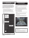
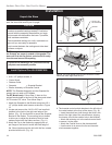
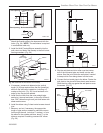
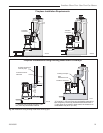
Fig. 23 Locate vent opening.
VO584-100a
VO584-100
Vent Opening
2/99 djt
9³⁄₈"
(240mm)
9³⁄₈"
(240mm)
7¹⁄₂"
(191mm)
Vent Opening - Combustible Wall
Vent Opening - Noncombustible Wall
ZCS103
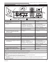
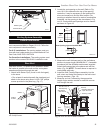
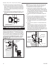
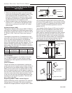
Zero Clearance Sleeve
& Firestop
12/6/99 djt
12”
(305mm)
Max. Length
Sleeve
#8 Sheet
Metal Screws
Firestop
ZCS103
Fig. 24 Assemble the wall sleeve and firestop.
Attach the firestop plate to the sleeve end with the
holes. (Fig. 24) NOTE: The wall sleeve is required
in combustible walls only.
3. Install the Wall Firestop/Sleeve assembly into the
wall cutout and fasten the firestop to the wall cutout
framing members. (Fig. 24)
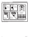
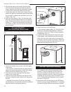
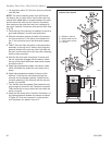
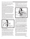
8. Slip the wall plate and trim collar over the interior
end of the horizontal pipe and install into the wall
sleeve. Seal the joint inside the wall plate if needed
to keep cold air from being drawn into the home.
9. Connect the horizontal pipe to the elbow. Fasten the
wall plate to the pipe with three sheet metal screws.
Slide the trim collar up against the wall plate to cover
the screws. (Fig. 27)
ST214
measure vertical vent
12/6/99 djt
X
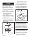
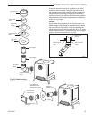
Fig. 25 Determine the vertical pipe length.
ST478
ST216
install pipe thru wall
12/6/99 djt
Trim Collar
Wall
Sleeve
Wall Plate
ST216
Fig. 27 Install the horizontal pipe and wall plate parts.
ST215
measure thru wall
12/6/99 djt
X
ST215
Fig. 26 Measure the horizontal length.
4. If necessary, measure to determine the vertical
length (X) of pipe required from the first (transition)
elbow to the wall cutout centerline, including a 2”
overlap at the joint. (Fig. 25) Use a hacksaw or tin
snips to trim the pipe as needed.
5. Install first the inner then the outer straight pipe
section(s), trimmed end down, to the point of the el-
bow. Drill 3 holes through each joint and fasten with
sheet metal screws.
6. Install the elbow using 3 sheet metal screws at each
joint.
7. Measure, and cut if necessary, the appropriate
length of pipe section needed to make the connec-
tion through the wall. Include a 2” overlap; i.e. from
the elbow to the outside wall face, about 2” or the
distance required if installing a second 90° elbow.
(Fig. 26)