


20
Stardance Direct Vent - Rear Vent Gas Heaters
20012950
• All vegetation within 36” (914 mm) that may interfere
with the draft.
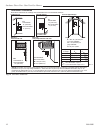
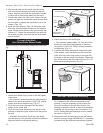
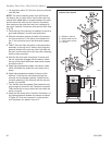
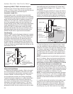
NOTE: The collar extending down from the Termina-
tion base is the air intake collar. Use the flex vent liner,
marked with a blue line, to connect between this collar
and the lower flue collar on the Transition Connector.
Also make sure the other flex vent liner is attached to
the upper Transition Connector collar and the Rain Cap.
(Fig. 33)
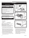
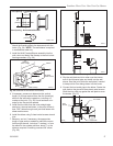
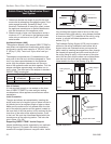
1. Clean the top of the chimney as needed, to ensure a
good seal between it and the vent termination.
2. Slide the insulation sleeves provided in the termina-
tion kit over the two 3” flex liners (to be attached to
the 3” flue collar and cap of the termination assem-
bly).
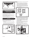
3. Feed 3” flex vent from the bottom of the termination
assembly up through the 4” sleeve. Apply high-tem-
perature sealant to the rain cap collar, and slide the
flex vent over the end of the rain cap collar, fastening
with the clamp provided.
4. Slide the flex liner back through the 4” sleeve until
the rain cap/collar engages over the sleeve. Attach
the cap to the sleeve with three sheet metal screws
provided in the kit.
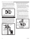
5. Apply high-temperature sealant over the air intake
collar, and attach the intake flex vent (blue) with a
clamp.
6. Apply high-temperature sealant to the top of the
chimney. Feed the two liners down through the
chimney flue and damper opening. Fasten the ter-
mination assembly to the chimney with the four set
screws (C) provided.
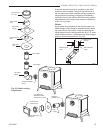
7. Trim the flex liners as needed. Each should be only
long enough to connect to the Transition Connector.
There should be no sag in either flex liner when the
stove is in place.
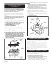
8. Attach the flex liners to the Transition Connector, us
-
ing high-temperature sealant and clamps as shown
in Figure 35. Prop the connector in rough position
until the heater is in place in front of it.
A
B
B
B
D
C
C
B
D
A
B
A
B
C
D
B
A
B
A
D
A
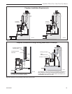
ST395
Fireplace
vent system
6/00
24"
(610 mm)
26"
(660 mm)
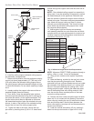
A = Sealant Locations
B = Sheet Metal Screws
C = Termination Screws
D = Clamps
Fireplace Vent System
ST395
Fig. 33 Fireplace vent system installation.