


9
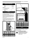
Pyromaster© H33BDVRRN/P
10004798
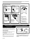
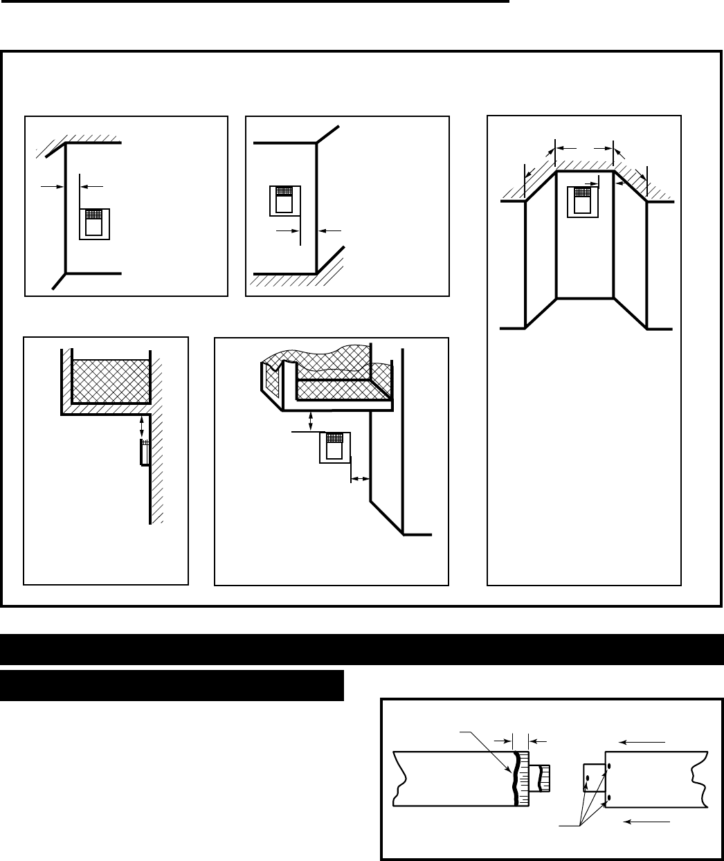
Outside Corner
Inside Corner
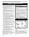
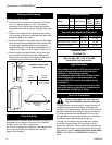
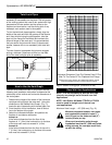
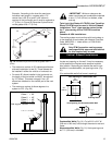
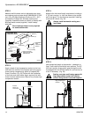
Termination Clearances
Termination clearances for buildings with combustible and noncombustible exteriors.
A =
Combustible
6"(152mm)
Noncombustible
2"(50mm)
B =
Combustible
6"(152mm)
Noncombustible
2"(50mm)
A
Balcony -
with no side wall
G =
Combustible&
Noncombustible
12"(305mm)
G
Balcony -
with perpendicular side wall
H = 24"(610mm)
J = 20"(508mm)
H
J
B
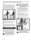
Recessed Location
C = Maximum depth of 48"
(1219mm) for recessed
location.
D = Minimum width for back wall
of a recessed location.
Combustible 38"(965mm)
Noncombustible 24"(610mm)
E = Clearance from corner in
recessed location.
Combustible 6"(152mm)
Noncombustible 2"(50mm)
C
D
C
E
V
V
Combustible &
Noncombustible
V
V
V
584-15
Fig. 8 Termination clearances.
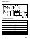
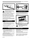
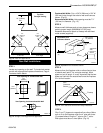
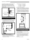
Crimped End Pipes
Before joining elbows and pipes apply a bead of high
temperature sealant to the crimped end of the elbow or
pipe. Join the pipes using a 2” (50mm) overlap and
secure the joints with three sheet metal screws. (Fig. 9)
Wipe off excess sealant.
Canadian Installations:
Venting system must be installed in accordance with
the current CSA-B149.1 installation code.
USA Installations:
The venting system must conform with local codes
and/or the current National Fuel Gas code ANSI
Z223.1.
Only venting components manufactured by CFM
Corporation can be used in Direct Vent systems.
General Information on Assembling DV Components
1" (25mm)
Screw Holes
Sealant
FP1175
Fig. 9 Apply a bead of high temperature sealant.
It is possible to use CFM Corporation 4” & 7” direct vent
crimped pipe and elbows with CFM Corporation 4” & 7”
twist-lock pipe. NOTE: The crimped pipe must be
used first.