


21
Pyromaster© H33BDVRRN/P
10004798
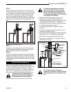
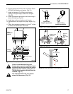
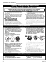
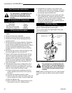
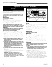
For units equipped with ‘HI/LO’ valves the flame
adjustment is accomplished by rotating the ‘HI/LO’
adjustment knob located near the center of the gas
control valve. (Fig. 38)
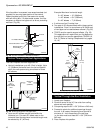
It is important to periodically perform a visual check of
the pilot and burner flames. Compare them to the
figures below. (Figs. 39-40)
If the flame patterns appear abnormal contact a
qualified service provider for service and adjustment.
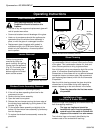
Flame Characteristics
Flame & Temperature Adjustment
Do not place any of the lava rock
material on the burner housing.
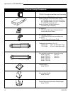
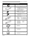
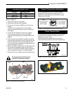
Log Identification Chart
Location H33BDVRRN/P
Front Right BA9
Rear Left BA7
Rear Fr Rt BA8
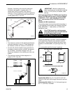
Refer to Figure 37
1. Remove the top louvre assembly.
2. Remove the window frame assembly.
3. Fit the rear front right log (BA8) onto the rear log
support.
Ensure the rear right end of the log is located
against the bracket bending up on the right side of
the support.
4. Fit the rear left log (BA7) onto the rear support.
Ensure the rear right end of the log is located
against bracket bending up on the right side of the
support.
5. Place the right rear log (BA9) in position by resting
the hole under the center of this log located over the
knob on the branch of the rear front right log, and
the front end of this log will also set against the back
wall of the deflector. (Fig. 37)
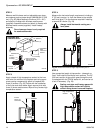
6. Scatter the ember material over the front area of the
burner housing assembly (Refer to Figure 38 for
details). Do not pack this material tightly, separate it
when unpacked and keep it in a loose condition.
7. Scatter the lava rock material around the firebox base.
BA7
Embers
BA8
BA9
LG259
Fig. 37 H33BDVRRN/P log placement.
LO
HI
Turn
counterclockwise
to decrease
flame height
Turn clockwise
to increase
flame height
Fig. 38 Flame adjustment knob for Honeywell valve.
HV102
3/8” - 1/2”
F584-703
Fig. 39 Correct pilot flame appearance.
LG260
Fig. 40 Correct flame appearance.