


10
Pyromaster© H33BDVRRN/P
10004798
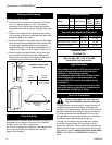
Twist Lock Pipes
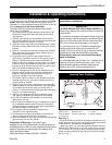
When using CFM Corporation twist-lock pipe it is not
necessary to use sealant on the joints. The only areas
of the venting system that need to be sealed with high
temperature silicone sealant are the collars on the
fireplace and termination, and the sliding joint of any
telescopic vent section used in the system.
To join the twist lock pipes together, simply align the
beads of the male end with the grooves of the female
end, then while bringing the pipe together, twist the
pipe until the flange on the female end contacts the
external flange on the male end. It is recommended
that you secure the joints with three (3) sheet metal
screws, however this is not mandatory with twist lock
pipe.
To make it easier to assemble the joints we suggest
putting a lubricant (Vaseline or similar) on the male
end of the twist lock pipe prior to assembly.
Male End
Female End
Screw Holes
TWL100
Fig. 10 Twist-lock pipe joints.
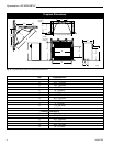
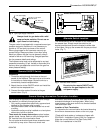
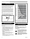
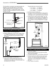
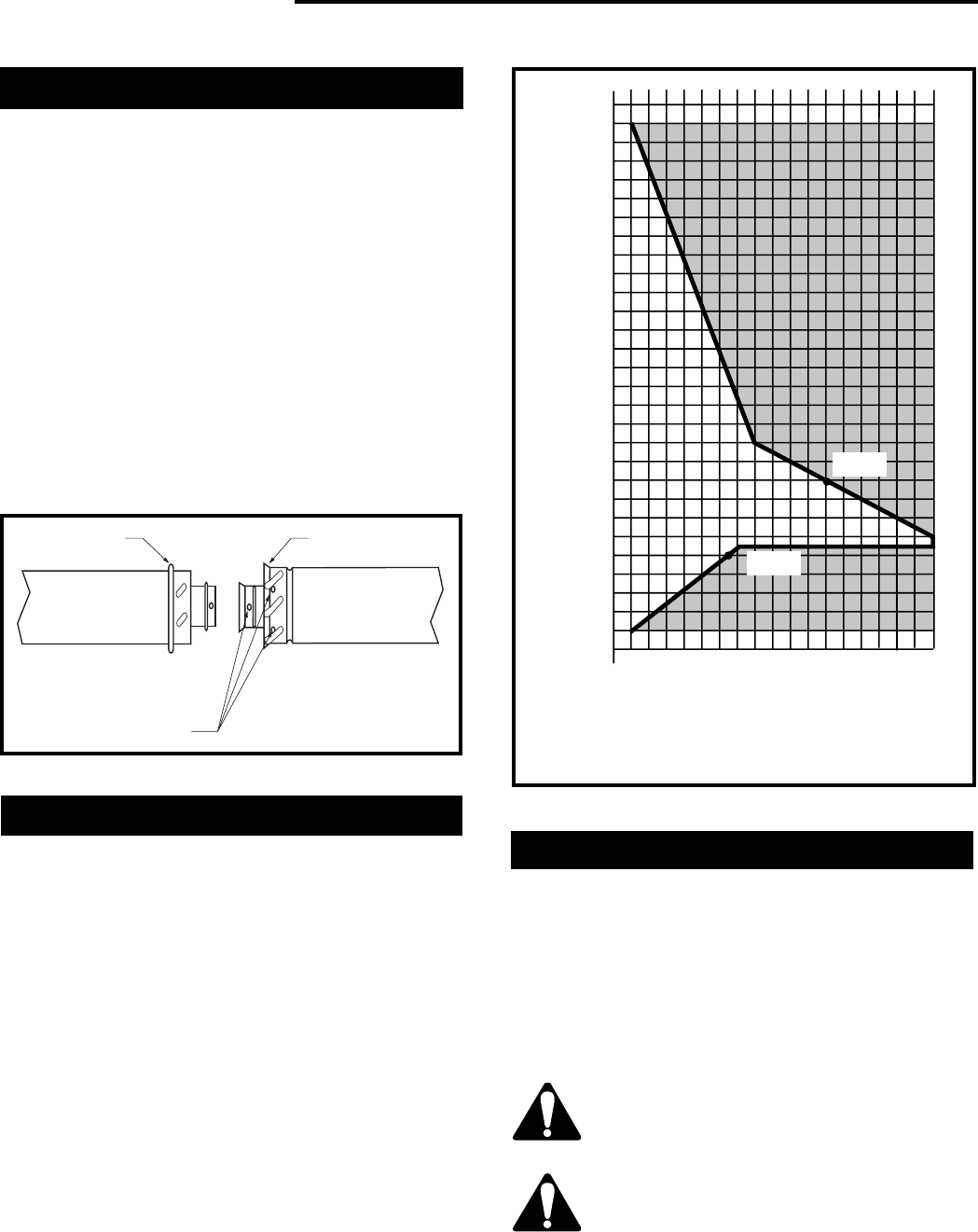
The vent chart should be read in conjunction with the
following vent installation instructions to determine the
relationship of the vertical and horizontal dimensions of
the vent system.
1. Determine the height of the center of the horizontal
vent pipe exiting through the outer wall. Using this
dimension on the Sidewall Vent Graph. (Fig. 11)
locate the point intersecting with slanted graph line.
2. From the point of this intersection, draw a vertical
line to the bottom of the graph.
3. Select the indicated dimension, and position the
fireplace in accordance with same.
Example A:
If the vertical dimension from the floor of the
fireplace is 11’ (3.4m) the horizontal run to the face
of the outer wall must not exceed 14’ (4.3m).
Example B:
If the vertical dimension from the floor of the unit is
7’ (2.14m), the horizontal run to the face of the outer
wall must not exceed 8¹⁄₂’ (2.6m).
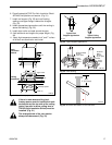
How to Use the Vent Graph
Horizontal Dimension From The Outside Face Of The
Wall To The Center Of The Fireplace Vent Flange
Sidewall vent graph showing the relationship between vertical
and horizontal dimensions for a Direct Vent flue system.
3
4
5
6
7
8
9
10
11
12
13
14
15
16
17
18
19
20
21
22
23
24
25
26
27
28
29
30
3 4 5 6 7 8 9 10 11 12 13 14 15 16 17 18 19 20
eg: A
eg: B
Vertical Dimension from the Floor of the Unit to
the Center of the Horizontal Vent Pipe
Fig. 11 Sidewall venting graph. (Dimensions in feet)
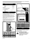
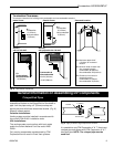
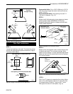
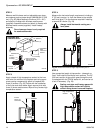
Rear Wall Vent Applications
Minimum clearance between vent pipes
and combustible materials is one (1”)
inch (25 mm) on the sides and two (2”)
inches (50 mm) on top.
When vent termination exits through
foundation less than 20” (508 mm) below
siding outcrop, the vent pipe must flush
up with the siding.
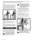
NOTE: It is not necessary to seal the vent pipe
joints for any straight out of the wall rear vent
applications.
NOTE: Vent Starter Kit Model 7TDVSK or 7DVSK
must be used in straight out of the wall rear
vent applications.
Maximum Vent Length......20” (508 mm) (Fig. 12)