


5
Pyromaster© H33BDVRRN/P
10004798
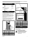
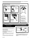
Appliance
Top.............................................. 0” (0 mm)
Bottom........................................ 0” (0 mm)
Side............................................ 0” (0 mm)
Back........................................... 0” (0 mm)
Venting
Concentric sections of DV Vent
Top, bottom & sides.................. 1” (25 mm)
Rear Vent Applications:
Top............................................ 2”
Sides......................................... 1”
Bottom...................................... 1”
Hearth
A hearth is not mandatory but is recommended for
aesthetic purposes. We recommend a noncombustible
hearth which projects out 12” (305mm) or more from
the front of the fireplace.
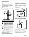
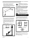
Cold climate installation recommendation:
When installing this unit against a
noncombustible exterior wall or chase, it
is mandatory that the outer walls be
insulated to conform to applicable
insulation codes.
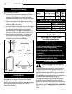
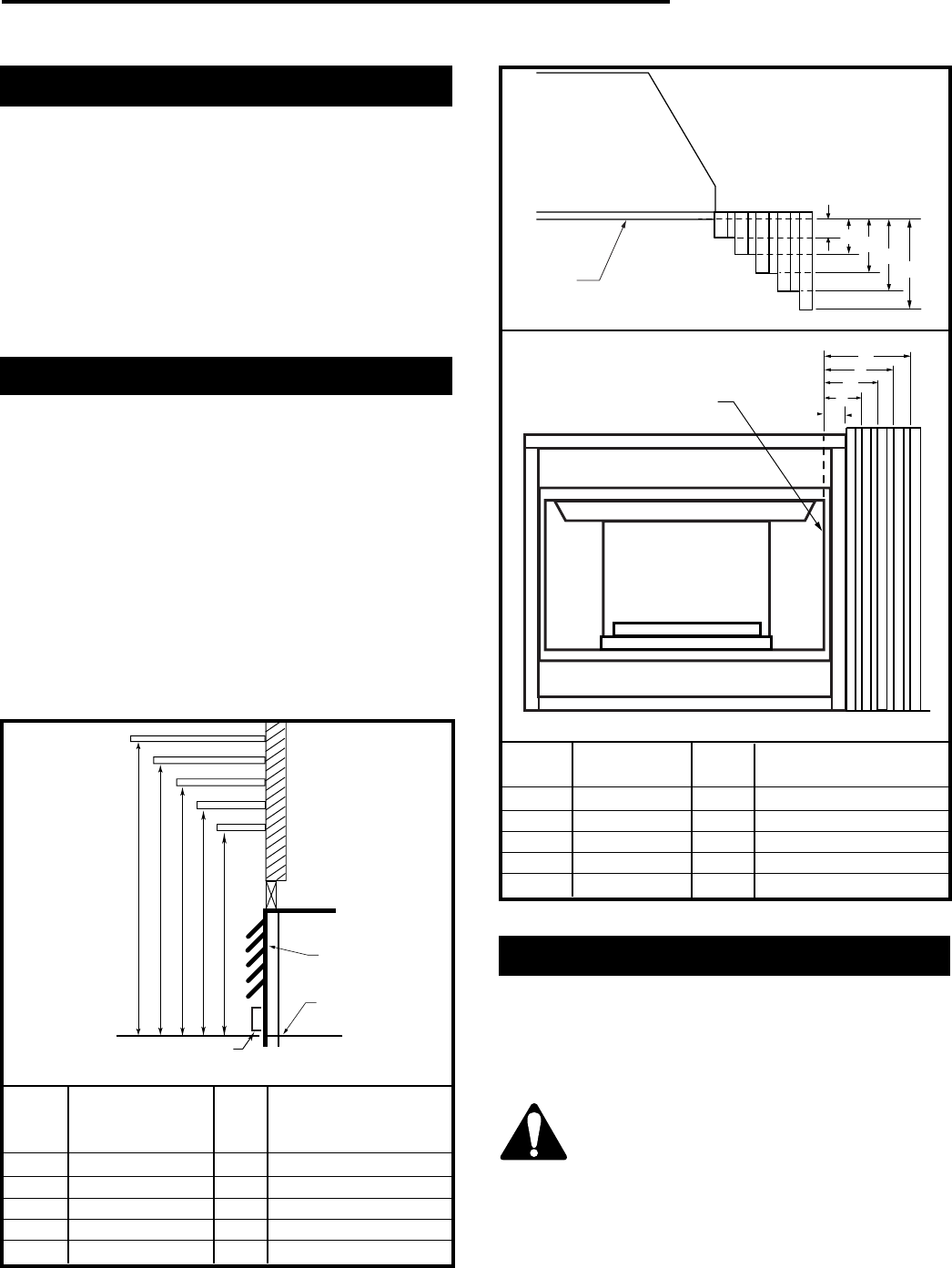
Mantels
The height that a combustible mantel is fitted above
the fireplace is dependent on the depth of the mantel.
This also applies to the distance between the mantel
leg (if fitted) and the fireplace.
For the correct mounting height and widths refer to
Figures 3a and 3b, and the following Mantel Charts.
The fitting of a bay window trim kit does not effect the
distances and reference points referred to in the
diagram and chart.
Noncombustible mantels and legs may be installed at
any height and width around the appliance. When
using paint or lacquer to finish the mantel, such paint
or lacquer must be heat resistant to prevent
discoloration.
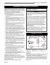
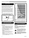
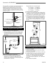
Clearance to Combustibles
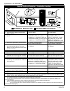
Mantel Chart
Mantel Shelf Mantel from Top
Ref. or Breast Plate Ref. of Comb. Chamber
Depth
V 10” (254mm) A 17” (432mm)
W 8” (203mm) B 15” (381mm)
X 6” (152mm) C 13” (330mm)
Y 4” (101mm) D 11” (279mm)
Z 2” (50mm) E 9” (229mm)
ABCDE
V
W
X
Y
Z
Fireplace
Top Louvre
Assembly
Top of Combustion
Chamber
Bottom of Door Triim
CFM146
Fig. 3a Combustible mantel minimum installation.
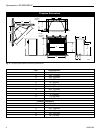
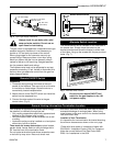
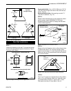
J
F
G
H
I
Mantel
Leg
O
N
M
L
K
Fig. 3b Combustible mantel leg minimum installation.
Mantel Mantel Leg from Side
Ref. Leg Depth Ref. of Comb. Opening
F 10” (254mm) K 11¹⁄₂” (292mm)
G 8” 9203mm) L 9¹⁄₂” (241mm)
H 6” (152mm) M 7¹⁄₂” (191mm)
I 4” (101mm) N 5¹⁄₂” (140mm)
J 2” (50mm) O 3¹⁄₂’” (89mm)
CFM170
Black
Surround
Face
Side of Combustion
Chamber
CFM164a