


44
DVRT41 Direct Vent Gas Fireplace
10006740
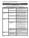
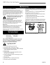
Remote Controls
Optional remote control units are available to control
different functions of the appliance.
Model Functions Controlled
MRC1 ON/OFF
MRC2 ON/OFF and Temperature
MRC3 ON/OFF and Temperature control with
a digital display and a programmable
24 hour clock
IMT Wall mounted thermostat control
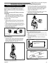
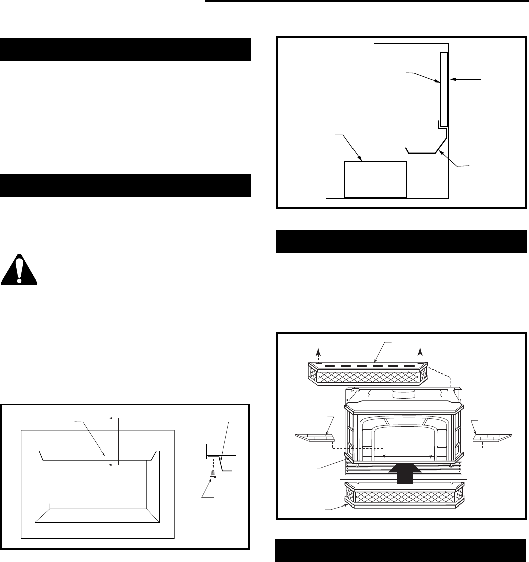
Ceramic Refractory Panels
Ceramic refractory panels are available to line the
firebox area.
Unit Kit Model
DVRT41 DVRT41CR
Take care when handling the refractory
panels as they are fragile until held in
place and supported.
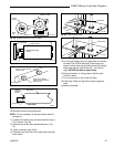
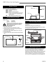
Installation Instructions
1. Remove window frame assembly and logs.
2. Remove three (3) screws securing heat shield to
combustion dome. (Fig. 75)
3. Place rear ceramic panel in back of unit. (Fig. 76)
4. Place side panels.
5. Replace heat shield, logs and window frame assem-
bly.
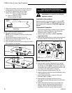
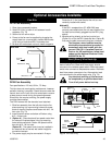
Decorative Bay Windows
The bay window kit is available for the DV360 only.
Installation
Remove the existing louvre assembly top.
Assemble the Bay Window Kit according to the instruc-
tions supplied with the kit. (Fig. 77)
Upper Grille Assembly
Ceramic
Refractory
Ceramic
Refractory
Window
Assembly
Base Grille
Assembly
FP1194
Fig. 77 Bay window.
Heat Shield
Section A
Heat
Shield
(3)
Screws
Side View
Section A
H103
Fig. 75 Heat shield.
Decorative Frame Trim
A selection of decorative frame trim kits are available
for mounting around the outside of the appliance to
enhance its visual effect on the room. Installation
instructions for each decorative frame trim are included
with the frame trim kit. Contact your authorized dis-
tributor for details of the trim kits and ordering informa-
tion for the trim kits applicable to this model appliance.
Rear
Ceramic Panel
Burner
Back of
Firebox
Rear Log
Support
H102
Fig. 76 Rear ceramic panel placement.